Download
1 / 36
580 likes | 1.58k Views
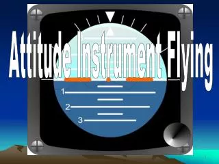
Attitude Instrument Flight. Attitude Instrument Flying . Attitude Instrument flying involves aircraft control by reference to its instruments rather than outside visual references Instrument scan is critical Slow methodical eye movements Know when and where to look for the task at hand

E N D
Attitude Instrument Flying • Attitude Instrument flying involves aircraft control by reference to its instruments rather than outside visual references • Instrument scan is critical • Slow methodical eye movements • Know when and where to look for the task at hand • Be relaxed • Create time for proper aircraft management
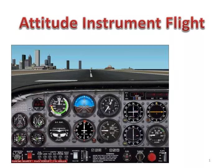
Fundamental Attitude Flying Skills • Instrument cross-check (scan) • Scan patterns • Inverted V • Radial • Rectangular or oval • Instrument focus • Two basic methods • Control and performance • Primary and supporting • Similar, but differ in their reliance on the attitude indicator and the role of other instruments in controlling the aircraft • Instrument interpretation • Aircraft control • All three are involved in all instrument flight maneuvers and must be integrated into unified, smooth, positive aircraft control inputs
Cross-Checking / Scanning • Continuous systemic focus on specific aircraft instruments for attitude and performance information • Doesn’t mean that eyes are moving like spinning slot machine reels • Make appropriate changes in airplane attitude based upon instrument observation
Cross-Checking / ScanningInverted V • Initial scan should be from the attitude indicator down to the turn coordinator, up to the attitude indicator, down to the VSI, and then back up to the attitude indicator
Cross-Checking / ScanningInverted V • Inverted V Scan is the initial scan • Step One - set a reasonable attitude and power setting for the desired maneuver • Remember the basic axiom of flight: Attitude + power = performance • Concentrate on the attitude indicator, set engine power by sound, and then glance at the engine's tachometer or manifold pressure gauge to fine-tune your power setting • Adjust the elevator trim coarsely if pressures become excessive.
Cross-Checking / ScanningInverted V • Step Two - Scan the turn coordinator (TC) and the vertical speed indicator (VSI) from the AI in an inverted V pattern • The TC and VSI are fine-tuners because of their sensitivity • TC will show a turn before the heading indicator • VSI will show a climb or descent before the altimeter • Your eyes should move from the AI to the TC, back to the AI, down to the VSI, and back to the AI • The scan should move at a slow speech rate - "and one and two, and one and two, and..."- e.g., that's how fast your eyes should move • When you say "and," look at the AI; when you say "one," look at the TC; when you say "two," look at the VSI • Key information while using the inverted-V scan is trend of motion information, rather than the specific numbers • Is the airplane doing what you want it to do - turning, flying level, climbing, or descending?
Cross-Checking / ScanningInverted V • Second priority is to validate the AI • Think in terms of aircraft systems • You are comparing electrical (TC) and vacuum bank information (AI), and you are comparing static-air (VSI) and vacuum pitch information (AI) • If a bank or pitch disagreement exists, look to an independent bank or pitch system in order to resolve the conflict • To resolve bank conflicts, use the magnetic compass. It will agree with either the AI or the TC • The instrument that disagrees is the problem. • You cannot use the heading indicator unless you check the suction gauge and confirm proper operation of the vacuum system • To resolve pitch conflicts, use the alternate static air system, air speed indicator and the altimeter • Pitch will agree with either the AI or the VSI • The instrument that disagrees is not reliable • IF static problem - you can’t use the altimeter or airspeed indicator, unless you replace the normal static-air system with the alternate static-air system if you have one, as it feeds from the same source • When a pitch or bank conflict develops, stop for a few seconds, and use system analysis to resolve the problem • False assumptions can result in loss of control Pitch conflict Bank conflict
Cross-Checking / ScanningInverted V • Cover the face of an erroneous instrument (carry post it notes in your flight bag) so that you aren't distracted by the incorrect information
Radial Scan • Step Three - Scan the other six-pack instruments • These are the tertiary instruments • Scan using the same slow eye movement as in the inverted V scan • Scan the instruments that have the numbers that you are trying to maintain – • Focus is on the important numbers – the quantitative information • Are you complying with ATC, your intentions / desires, what the navcharts require? • If you do not like what you see, • Return to Step One and change attitude and /or power • Return to Step Two for trend of motion and for AI validation • Return to the radial scan (Step Three) for the numbers
Cross-Checking / ScanningRadial • In the radial scan you will spend 80 to 90% of the time looking at the attitude indicator with only quick glances at one of the other flight instruments • Your eyes always go from the AI to another flight instrument and never directly between the other flight instruments • The maneuver being performed at any given time determines which instruments are included in the scan pattern
Cross-Checking / ScanningRectangular or Oval • Step Four • Transition from a radial scan to a circular scan and fine-trim the elevator and rudder trim • Imagine a rectangular pattern flowing over all six primary flight instruments • Used because the radial scan is very fatiguing • Radial scan is used only when you are redirecting the airplane - changing attitude and/or power • Rectangular scan is more relaxing, and allows for small corrections as you evaluate the instruments • Use the rectangular scan pattern whenever the airplane is in stabilized, straight-and-level flight
Cross-Checking / ScanningRectangular • Rectangular scan covers all instruments equally, regardless of its importance to the maneuver being performed • Lengthens the time it takes for you to return to the critical instruments for a maneuver
Common Cross-Check Errors • Fixation - staring at a single instrument • Omission of an instrument from your scan • Emphasis on a single instrument rather than the necessary combination of instruments
Control and Performance Method • Aircraft controlled through the aircraft’s attitude and power • Fundamental precept -> Attitude + Power = Performance • Instrument categories • Control • Performance • Navigation instruments. • Control Instruments • Display immediate attitude and power indications • Permit precise attitude and power adjustments • Control is determined by reference to the attitude indicator and power indicators • Power indicators include tachometer, manifold pressure, etc.
Control and Performance Method • Performance Instruments • Indicate the aircraft’s actual performance • AI and Tach/MP • Performance instruments include • Altimeter • Airspeed indicator • VSI • Heading indicator • Turn-and-slip indicator • Navigation Instruments • Indicate the aircraft’s position • Navigation instruments include • CDI • HSI • Glide slope indicators • Bearing pointers • GPS displays
Control and Performance Method • Establish Rough Settings • Set your attitude and a power setting with the control instruments (AI and tach/MP gauge) that will produce the approximate performance desired • Known attitudes and approximate power settings will reduce workloads • Trim • Trim to relieve control pressures • Essential for smooth, precise aircraft control and allows you to divert attention to other things with minimized changes to aircraft attitude • Cross-check • Cross-check performance instruments to determine if the rough settings are providing the desired performance • Involves both seeing and interpreting the instruments • If a deviation is noted, determine the magnitude and direction of adjustment required • Correct • Make any necessary attitude or power setting changes with the control instruments as necessary • Cross check performance instruments
Control and Performance Method • Attitude Control • Must maintain a constant attitude, and know when and by how much to change the attitude • Smoothly change attitude by precise amounts, when required • Accomplished by using the attitude indicator which provides an immediate, direct indication of any change in aircraft pitch or bank. • Pitch Control • Observe changes to the “pitch attitude” of the AI’s indicator in relation to the horizon • Know indicator gradients 2.5, 5 and 10 degree lines / estimate bar widths • Bank Control • Observe changes to the “bank attitude” or bank pointers on the edge of the AI • Bank scale is normally referenced marked at 0°, 10°, 20°, 30°, 60°, and 90° • AI vs ADI (sky pointer) • Normally, use a bank angle that approximates the degrees to turn, not to exceed 30°
Control and Performance Method • Power Control • Establish or maintain desired airspeeds in coordination with attitude changes through power / throttle adjustments • Refer to the power indicators • Learn approximate power settings by sight, sound and feel and then cross-check the power indicators (MP / Tach) to establish a more precise setting
Primary and Supporting Instrument FAA Method • Attitude control can be thought of in terms of pitch, bank, power, and trim control, as all maneuvers involve motion about all 3 axes - lateral (pitch), longitudinal (bank/roll), and vertical (yaw) • Instruments are grouped as they relate to control function and aircraft performance as follows: • Pitch Instruments • Attitude indicator, altimeter, airspeed indicator, VSI • Bank Instruments • Attitude indicator, heading indicator, magnetic compass, turn coordinator • Power Instruments • Airspeed indicator. engine instruments, manifold pressure gauge, tachometer/RPM • Certain instruments are key in each maneuver or condition of flight • Primary instruments provide the most pertinent and essential information. • Supporting instruments back up and supplement the information shown on the primary instruments
Partial Panel Scan TechniqueLoss of Vacuum • Turn coordinator becomes the master instrument • Roll and balance information from the T/C • Pitch information from the AI is lost – Get pitch information indirectly from the remaining instruments, namely the ASI, ALT and VSI • Use a rectangular scan originating from the T/C
Partial Panel Scan TechniqueLoss of Vacuum • Climbing • Set climb power • Gentle pitch movements until the desired air speed is obtained then trim • Descending • Reduce power, allowing the pitch to naturally change, until the required rate of descent is achieved • No change in trim should be required, unless a specific airspeed is required for the descent, in which case reduce power, hold attitude for required speed, then descent in a trimmed condition
Partial Panel Scan TechniqueLoss of Vacuum • Turning • Will need to rely on turn coordinator and compass • Remember compass errors during turns • Turn coordinator is primary bank instrument • The compass also reads in the reverse sense to the DI (Look at the VOR or GPS to decide which direction to turn) • Use standard rate turns on TC and time for 3 degrees per second to come out at approximately the correct heading • Turn Procedure • Check current heading on the compass • Calculate the number of seconds for the turn (max 60 seconds), and establish the direction of the turn • Establish standard rate turn, start timing and maintain turn rate • Roll wings level when the time is complete • Fly straight and level for a couple of seconds to allow the compass to settle • Check correct heading has been achieved. Repeat if necessary to fine tune heading
Partial Panel Scan TechniqueLoss of Vacuum • Approach • On partial panel use 1/2 standard rate turns on approach • Request a No-Gyro Approach • ATC will instruct you to turn left or right, using the turn coordinator, and then tell you when to stop the turn. • ATC will expect you to make standard rate turns and to start and stop turns as soon as you are instructed. • ATC will notify you when you are on final approach and you will be expected to make 1/2 standard rate turns. • Use GPS as an alternative to the compass • Movements on partial panel should be smooth and gradual
Pitot / Static System Failure • Pitot / static system failure may cause erratic and unreliable AI, ASI and VSI instrument indications • Procedure • Consider pitot heat • Select alternate static source • In the absence of an alternate static source, in an unpressurized aircraft, you can break the glass on the VSI • Breaking the VSI glass provides an alternate source if static pressure to the altimeter and airspeed indicator • May cause some errors
Pitot / Static System Failure • ASI uses inputs from both pitot and static system and therefore will be affected by a failure in either system • If the pitot tube is blocked (along with its drain hole) — by ice, an insect or some other foreign material • Likely not to be noticed in level flight • In a climb or a descent, however, the ASI will act like an altimeter • If only the pitot tube (but NOT the drain) is blocked the airspeed will decrease, likely to near zero • Since the altimeter and VSI rely only on static pressure input, they won't be affected by blockages of the pitot tube
Pitot / Static System Failure • A blocked static port will cause varying symptoms depending upon how much blockage there is and the altitude at which it occurs • Generally, will cause the airspeed indicator to increase with decreasing altitudes and decrease during a climb – a reverse altimeter effect • If the static port is blocked at a relatively high altitude there will be an increasing difference between static and pitot pressure as the airplane descends • An altimeter affected by a blocked static system will continue to show the same reading it had when the blockage occurred regardless of actual altitude • Likewise the VSI will usually not change with a blocked static system
Pitot / Static System Failure • Remember attitude + power = performance • Use the AI, as long as you have vacuum, to keep the airplane level. Set pitch and power • Consider backup altimeter • GPS • Altimeter watches, sky diving altimeters, etc. • Don’t allow your attention to become fixated on any one instrument or system
Aircraft Control • Maintain aircraft attitude or change it by moving the appropriate controls • Aircraft control is composed of four aspects: • Pitch - elevators • Bank - ailerons • Power • Trim - relieves control pressures to eliminate constant control pressures which produces tension, distracts the pilot’s attention from cross-checking, and contributes to abrupt and erratic attitude control
Aircraft Control Errors • Improper instrument interpretation • Improper control application • Failure to establish proper attitude / performance • Improper entry or level off technique • Don’t chase the needles • Failure to anticipate required power changes • Watch for ballooning on level off • Failure to use an accelerated cross check as the maneuver begins and ends • Failure to trim or poor trim technique • Failure to relax rudder pressure / tension - excessively strong grip on the control column resulting in an over-control situation
PTSBasic Instrument Flight Skills • Exhibits adequate knowledge of the elements related to attitude instrument flying during straight-and-level flight, climbs, turns, and descents while conducting various instrument flight procedures. • Maintains altitude within ±100 feet during level flight, headings within ±10°, airspeed within ±10 knots, and bank angles within ±5° during turns. • Uses proper instrument crosscheck and interpretation, and apply the appropriate pitch, bank, power, and trim corrections when applicable.
PTSPartial Panel • Exhibits adequate knowledge of the elements relating to recognizing if primary flight instruments are inaccurate or inoperative, and advise ATC or the examiner • Advises ATC or examiner anytime that the aircraft is unable to comply with a clearance • Demonstrates a nonprecision instrument approach without the use of the primary flight instrument using the objectives of the nonprecision approach • Demonstrates an appropriate level of single-pilot resource management skills
Disclaimer • Instrument flight can be dangerous. Do not rely solely on this presentation – PROFESSIONAL INSTRUCTION IS REQUIRED • The foregoing material should not be relied upon for flight • ALTHOUGH THE ABOVE INFORMATION IS FROM SOURCES BELIEVED TO BE RELIABLE SUCH INFORMATION HAS NOT BEEN VERIFIED, AND NO EXPRESS REPRESENTATION IS MADE NOR IS ANY TO BE IMPLIED AS TO THE ACCURACY THEREOF, AND IT IS SUBMITTED SUBJECT TO ERRORS, OMISSIONS, CHANGE