Download
1 / 12
130 likes | 492 Views
EMC-Filter and Impedance Matching for MF RC500 and SL RC400. Antenna Design. 50 Short Range antenna. Directly Matched antenna (700 ). 50 Full Range antenna. Antenna Design. EMC-Filter and Impedance Matching of. RC500 / RC400. Zi. Tx1. Zi: complex source impedance

E N D
EMC-Filter and Impedance MatchingforMF RC500 and SL RC400 Antenna Design
50 Short Range antenna Directly Matched antenna (700 ) 50 Full Range antenna Antenna Design EMC-Filter and Impedance Matchingof
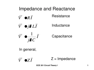
RC500 / RC400 Zi Tx1 Zi: complex source impedance Zi = Ri(f)+jX(f) Vi TVss EMC-Filter + Impedance Matching to 50(Short Range) Start: Output stage of the reader is represented by a model
+ Matching RC500 / RC400 EMC Filter L0 Zi Tx1 C1 Z = 50 Ohm Zi: complex source impedance Zi = Ri(f)+jX(f) C0 Vi TVss EMC-Filter + Impedance Matching to 50 (Short Range)
13.56 MHz Z = 50 L0 Tx1 Maximum Power C1 Z RC500 RC400 C0 Minimum harmonics TVss S22 L0 = 1 H C0 = 68 pF C1 = 68 pF S21 ~ Power Out EMC-Filter + Impedance Matching to 50 (Short Range)
Rx-Circuit RC 500 RX RC 400 R C 1 3 VMID R 2 C 4 AVSS Tx 50 TX1 L C 0 1 C 0 TVSS TVSS Tx-circuit TX2 Rx-Circuit: R1 = 470 … 2,7 k R2 = 820 C3 = 15 pF C4 = 100 nF Tx-Circuit: L0 = 1 H C0 = 68 pF C1 = 68 pF EMC-Filter + Impedance Matching to 50 (Short Range)
EMC Filter + Matching RC500 / RC400 Tx1 Zi L0 C0 Vi Zi: complex source impedance Zi = Ri+jX Z 700 Ohm TVss Vi C0 L0 Tx2 Zi EMC-Filter + Impedance Matching to 700(Directly Matched)
Rx-Circuit RC 500 RX RC 400 R C 1 3 VMID R 2 C 4 AVSS TX1 L Tx-Circuit 0 C 0 Z 700 Ohm GND TVSS 0 C 0 L TX2 Rx-Circuit: R1 = 470 … 2,7 k R2 = 820 Tx-Circuit: L0 = 1 H C0 = 136 pF C3 = 15 pF C4 = 100 nF EMC-Filter + Impedance Matching to 700(Directly Matched)
EMC Filter + Matching RC500 / RC400 Tx1 Zi L0 C1 C0 Vi TVss Zi: complex source impedance Zi = Ri+jX Vi C0 L0 50 Tx2 C1 Zi EMC-Filter + Impedance Matching to 50(Full Range)
Rx-Circuit RC 500 RX RC 400 R C 1 3 VMID R 2 C 4 AVSS TX1 L C 0 1 C 0 TVSS 0 C 1 0 C L 50 TX2 Tx-circuit Rx-Circuit: R1 = 470 … 2,7 k R2 = 820 Tx-Circuit: L0 = 1 H C0 = 68 pF C1 = 82 pF C3 = 15 pF C4 = 100 nF EMC-Filter + Impedance Matching to 50(Full Range)
Antenna Circuitry RC500 RC400 (or other Reader) Rx Rx- Circuit Tx Matching Matching Antenna EMC- Filter Antenna Design EMC-Filter and Impedance MatchingSummary
1) Matching - 50-Short-Range - Directly-Matched - 50-Full-Range 2) Resonance 3) Tuning 4) Q-factor with the same receive circuit 5) Finetuning 6)Receive Circuit 6) Receive Circuit Antenna Design EMC-Filter and Impedance MatchingSummary