Download
1 / 54
560 likes | 1.25k Views
Real-Time Measurement of Prehensile EMG signals. Master Thesis Saksit Siriprayoonsak Supervisor: Marko Vuskovic Department of Computer Science San Diego State University August 24, 2005. Contents. Introduction EMG Overview Apparatus for EMG Measurement

E N D
Real-Time Measurement of Prehensile EMG signals Master Thesis Saksit Siriprayoonsak Supervisor: Marko Vuskovic Department of Computer Science San Diego State University August 24, 2005 Copyright 2005 by Saksit Siriprayoonsak
Contents • Introduction • EMG Overview • Apparatus for EMG Measurement • Implementation of EMG Capture Program • Experimental Results • Conclusion Copyright 2005 by Saksit Siriprayoonsak
A research in Robotics Laboratory, SDSU Multifunctional Prosthetic Hand Control Copyright 2005 by Saksit Siriprayoonsak
Object of Thesis Main purpose: • Design and develop hardware and software for measuring surface EMG signals from real human muscles in real-time. Immediate application: • To control the existing SDSU multifingered robot hand. Copyright 2005 by Saksit Siriprayoonsak
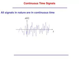
EMG Overview • EMG – Electromyography • Electromyography measures the electrical impulses of muscles at rest and during contraction. • Amplitudes of EMG signal range between 0 to 10 mV (peak-to-peak) or 0 to 1.5 mV (rms). • Frequency of EMG signal is between 0 to 500 Hz. • The usable energy of EMG signal is dominant between 50-150 Hz. Source: http://www.delsys.com/library/papers/SEMGintro.pdf Copyright 2005 by Saksit Siriprayoonsak
Amplification of EMG Signals Factors to be considered: • Boost signal to TTL standard level (± 5 V.) • Enough gain • Noise/Artifact problem • Filter, stability of electrodes attached to skin, proper grounding • DC offset or bias problem • Bias adjustment • Power consumption • Consume less current Copyright 2005 by Saksit Siriprayoonsak
EMG Measurement Stages Copyright 2005 by Saksit Siriprayoonsak
EMG Amplifier: Electrode and Extension • Stereo phone wire with 3 conductors • Positive input to preamplifier • Negative input to preamplifier • Shield as the input of body reference circuit • Velcro strap for securing the electrode to the skin Copyright 2005 by Saksit Siriprayoonsak
EMG Amplifier: Electrode and Extension (cont.) • Plastic piece and snap on for holding electrode elements • Dimension of 1 inch between electrode contacts • 4 electrode extensions and 1 body reference extension • Total of 9 electrode contacts Copyright 2005 by Saksit Siriprayoonsak
Power Supply Unit Circuit EMG Amplifier: Power Supply • Dual Supply • Positive Power Supply • Negative Power Supply • Two 9-volt batteries connected in series • Capacitors provide stability of electrical current. Copyright 2005 by Saksit Siriprayoonsak
EMG Amplifier: Preamplifier • Industry standard instrumentation amplifier op-amp (INA2128) • Accuracy: providing high bandwidth at high gain and output offset current • Differential amplifier circuit with 2 inputs • High gain to boost the EMG signals • Body Reference Circuit or Feed Back (OPA2604) Copyright 2005 by Saksit Siriprayoonsak
BURR-BROWN INA2128 Application Information EMG Amplifier: Preamplifier (cont.) Copyright 2005 by Saksit Siriprayoonsak
Preamplifier with Body Reference Circuit (1 channel) EMG Amplifier: Preamplifier (cont.) Gain Equation: Find RG at Gain = 1,000: Find Gain at RG = 22 ohm: Copyright 2005 by Saksit Siriprayoonsak
Inverting Summing Amplifier Circuit Sign Changing Circuit (Inverting Amplifier Circuit) EMG Amplifier: Averaging Body Reference Circuit • Common body reference circuit for 4 channels • Using summing amplifier circuit and sign changing circuit For independent R1, R2, R3, and R4: For independent R1, and R2: For R1= R2= R3= R4: For R1= R2: Copyright 2005 by Saksit Siriprayoonsak
EMG Amplifier: Average Body Reference Circuit (Cont.) Average Body Reference Circuit Common Body Reference Output: Copyright 2005 by Saksit Siriprayoonsak
EMG Amplifier: Filter • Suppress noise that has been amplified by the preamplifier • Help to sink any DC current that cause bias to the output • Select particular signal frequency range • Use RC High Pass Filter of 12 Hz Copyright 2005 by Saksit Siriprayoonsak
Cutoff Frequency: Cutoff Frequency of 12 Hz: RC High Pass Filter Cutoff Frequency of 12Hz EMG Amplifier: Filter (cont.) RC High Pass Filter Copyright 2005 by Saksit Siriprayoonsak
EMG Amplifier: Amplifier and Bias Adjustment • Provide abilities to amplify and adjust reference level of output signals • Individual amplifier and bias adjustment unit for each channel • Use Non-Inverting circuit for amplifier unit • Use Voltage Follower Offset Adjustment circuit for bias adjustment unit • Provide Gain of 21 times • Provide Offset of ± 9 volts Copyright 2005 by Saksit Siriprayoonsak
Non-Inverting Amplifier Circuit EMG Amplifier: Amplifier and Bias Adjustment (cont.) Non-Inverting Output: Copyright 2005 by Saksit Siriprayoonsak
Amplifier Circuit with Gain Adjustment Amplifier Circuit with Gain Adjustment At : At : EMG Amplifier: Amplifier and Bias Adjustment (cont.) Amplifier Gain: Copyright 2005 by Saksit Siriprayoonsak
volts ) Case 1: at 0% of : ( ohms; volts ) Case 2: at 50% of : ( ohms; Offset Adjustment for Voltage Follower Case 3: at 100% of : ( ohms; volts ) EMG Amplifier: Amplifier and Bias Adjustment (cont.) Output of the circuit: Copyright 2005 by Saksit Siriprayoonsak
volts ) Case 1: at 0% of : ( ohms; volts ) Case 2: at 50% of : ( ohms; Bias Adjustment Circuit Case 3: at 100% of : ( ohms; volts ) EMG Amplifier: Amplifier and Bias Adjustment (cont.) Output of the circuit: Copyright 2005 by Saksit Siriprayoonsak
A/D Interface Card • NI 6220 M-Series Multifunction DAQ • Clock Speed: 8 Hz, up to 1 MHz • Analog Input Resolution: 16 bits • Number of Analog Input Channels: 8 Copyright 2005 by Saksit Siriprayoonsak
Final Product Assembly • Circuit designed and tested on breadboard • Schematic created by Multisim8 • PCB layout created by Ultiborad7 Copyright 2005 by Saksit Siriprayoonsak
Final Product Assembly (cont.) • A schematic diagram is drawn using Multisim8. • Netlist contains all circuit connections. • Netlist is transferred to Ultiboard7 for PCB layout. • PCB is a double layer (top copper layer and bottom copper layer) • Through holes connect between 2 layers. Copyright 2005 by Saksit Siriprayoonsak
PCB shipped by the manufacturer Final Product Assembly (cont.) Copyright 2005 by Saksit Siriprayoonsak
PCB after soldering Final Product Assembly (cont.) Copyright 2005 by Saksit Siriprayoonsak
Calibration Procedure • Each channel is individually calibrated. • Input is equal to output (100 mV.) • If an arbitrary gain is needed, the output is desired gain value multiplied by input. Copyright 2005 by Saksit Siriprayoonsak
EMG Capture • Provides 3 play modes: Real-Time, Record, and Playback mode. • Able to save and open EMG data to/from file. • Display features: • Voltage scales • Time scales • Readout of exact values Copyright 2005 by Saksit Siriprayoonsak
EMG Capture: User Interface Copyright 2005 by Saksit Siriprayoonsak
EMG Capture: Main Parameter Subpanel • Working with Real-Time mode and Record mode. • Maximum Buffer Size (Samples per Channel) • Sampling Rate (Hz) Copyright 2005 by Saksit Siriprayoonsak
EMG Capture: Play Mode Copyright 2005 by Saksit Siriprayoonsak
EMG Capture: Real-Time Mode START • Start real time mode • Stop real time mode • Freeze output display for examine interesting segments or save the data • Resume real time mode • Save data in buffer to file STOP Pause Resume Save Copyright 2005 by Saksit Siriprayoonsak
EMG Capture: Record Mode • Start to Record the signals in specific time range in seconds. • Save the data to file START Save Copyright 2005 by Saksit Siriprayoonsak
Standard window open dialog EMG Capture: Playback Mode - Open EMG data file (.emg) Open Copyright 2005 by Saksit Siriprayoonsak
EMG Capture: Voltage Scale • Voltage scale is independent for each channel. • Alternative voltage scales: • 200 mV/Div. • 500 mV/Div. • 1 V/Div. • 2.5 V/Div. • 5 V/Div. Copyright 2005 by Saksit Siriprayoonsak
EMG Capture: Time Scale • All channels use the same time scale • Alternative time scales: • 1 mSec/Div. • 5 mSec/Div. • 10 mSec/Div. • 50 mSec/Div. • 100 mSec/Div. • 200 mSec/Div. • 400 mSec/Div. Copyright 2005 by Saksit Siriprayoonsak
EMG Capture: Time Slider • Scroll time slider to view data from beginning to the end. • The numbers on the left and right corner correspond to the time stamp of the first and the last sample shown on the output display screen. • ‘5.416’ is 5 seconds and 416 milliseconds. Copyright 2005 by Saksit Siriprayoonsak
EMG Capture: Readout • Read extract value at pink vertical line • Need not to compute the value of scale • Unit: Time (sec) , Voltage (V) Copyright 2005 by Saksit Siriprayoonsak
EMG Capture: Output Display • Displays 4 channels • Voltage: 4 divisions • 2 positive divisions • 2 negative divisions • Time: 15 divisions • Maximum Display: • ±10 volts with 5 volts/Div. • 6 seconds with 400 mSec/Div Copyright 2005 by Saksit Siriprayoonsak
EMG Capture: Status Bar • Guide user through the usage • Display important message eg. Number of samples that went into the buffer. Copyright 2005 by Saksit Siriprayoonsak
EMGC Implementation • Developed by using Microsoft Visual C++ tool • GUI developed with MFC (Microsoft Foundation Class) library • Runs on Windows 2000 machine which has A/D interface card installed • A/D Interface Card: Multifunction Data Acquisition (DAQ), M-6220 series from National Instrument Company Copyright 2005 by Saksit Siriprayoonsak
struct SOutputData { int output_ii; //Iteration start from 0 double time; //Time stamp in Second double volt1; //Voltage value for CH1, CH2, CH3, and CH4 double volt2; double volt1; double volt1; }; CArray <SOutputData, SOutputData> dumpDataArray; EMGC Implementation: Output Buffer Structure • CArray class from MFC Library used to store input signal data. • CArray can dynamically shrink and grow if necessary. Copyright 2005 by Saksit Siriprayoonsak
//For Calculation double voltScaleSet[5] = {5.0, 2.5, 1.0, 0.5, 0.2}; //unit in volt/div //For Screen Display CString voltScaleStrMap[5] = {“5 Volt/Div”, “2.5 Volt/Div”, “1 Volt/Div”, “500 mVolt/Div”, “200 mVolt/Div”}; EMGC Implementation: Creating Voltages and Time Scales • Use spin control to select the scales. • Spin control increase/decrease spin value by a specific number of steps. • Use spin value as the index of scale array. Copyright 2005 by Saksit Siriprayoonsak
EMGC Implementation: Draw Grid for Graph Output • Use CDC class (Class Device-Context object) to draw output on the screen. • The CDC class is a class from the MFC library. • CDC provides various kinds of drawing functions (working with drawing tool, converting the coordinates, drawing rectangles, drawing circles, drawing text, changing the color) Copyright 2005 by Saksit Siriprayoonsak
private: //Variables for drawing output int _maxTimeDiv; //Max number of divisions to display on Output-Panel int _maxVoltDiv; //time axis = 15 divisions //volt axis = 4 divisions (2 positive Divs) // (2 negative Divs) int _ptsPerDiv; //How many points are there in 1 division. //1 point = 0.1 milimeter //Default 100 points = 1 division is 1 cm wide // ** Base on: Display Resolution= 1024 x 768 int _maxDrawPtsX; // _maxTimeDiv*_ptsPerDiv, Max Drawing Point for // time int _maxDrawPtsY; // _maxTimeDiv*_ptsPerDiv, Max Drawing Point for volt //Default x=1500, y=400 EMGC Implementation: Draw Grid for Graph Output (cont.) Copyright 2005 by Saksit Siriprayoonsak
EMGC Implementation: Draw Grid for Graph Output (cont.) Copyright 2005 by Saksit Siriprayoonsak
Function CEMGCDlg::voltToDC() Function CEMGCDlg::voltToDC() EMGC Implementation: Drawing Graph Output The output can be drawn by using (x,y) coordinate to specify position to draw. Copyright 2005 by Saksit Siriprayoonsak
EMGC Implementation: Saving Data Buffer To File • File Extension (‘.emg’) • Header line contains • Sampling rate (HZ) • Record time period (sec) • Data speparate by a ‘space’. • Each record separated by a ‘carriage return’ (put in front). Copyright 2005 by Saksit Siriprayoonsak
struct SOutputData { int output_ii; //Iteration start from 0 double time; //Time stamp in Second double volt1; //Voltage value for CH1, CH2, CH3, and CH4 double volt2; double volt1; double volt1; }; CArray <SOutputData, SOutputData> dumpDataArray; EMGC Implementation: Read File To Data Buffer • Read header file • Sampling rate -> computes sampling period • Record time period -> verifies the data file (completed or in completed) • Store data in buffer (dumpDataArray) Copyright 2005 by Saksit Siriprayoonsak