Download
1 / 37
370 likes | 472 Views
Binary Decision Diagrams and Symbolic Model Checking. Randy Bryant CMU Ed Clarke CMU Ken McMillan Cadence Allen Emerson U Texas. http://www.cs.cmu.edu/~bryant. Binary Decision Diagrams. Restricted Form of Branching Program Graph representation of Boolean function Canonical form

E N D
Binary Decision DiagramsandSymbolic Model Checking Randy Bryant CMU Ed Clarke CMU Ken McMillan Cadence Allen Emerson U Texas http://www.cs.cmu.edu/~bryant
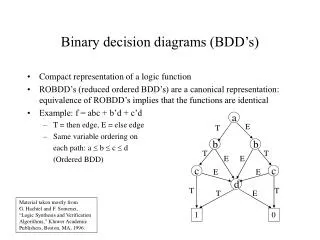
Binary Decision Diagrams • Restricted Form of Branching Program • Graph representation of Boolean function • Canonical form • Simple algorithms to construct & manipulate • Application Niche • Problems expressed as Quantified Boolean Formulas • A lot of interesting problems are in PSPACE • Symbolic Model Checking • Prove properties about large-scale, finite-state system • Successfully used to verify hardware systems
0 1 0,1 1 1 Boolean Function as Language • View n-variable Boolean function as language {0,1}n • Reduced DFA is canonical representation Language DFA Truth Table { 011, 101, 111 }
x1 x1 x1 0 1 x2 x2 x2 x2 0,1 x3 x3 1 x3 1 1 0 1 1 From DFA to OBDD • Canonical representation of Boolean function • Two functions equivalent if and only if graphs isomorphic • Desirable property: simplest form is canonical.
Representing Circuit Functions • Functions • All outputs of 4-bit adder • Functions of data inputs • Shared Representation • Graph with multiple roots • 31 nodes for 4-bit adder • 571 nodes for 64-bit adder • Linear growth
Linear Growth Exponential Growth Effect of Variable Ordering Good Ordering Bad Ordering
Sample Function Classes • General Experience • Many tasks have reasonable OBDD representations • Algorithms remain practical for up to 500,000 node OBDDs • Heuristic ordering methods generally satisfactory Function Class Best Worst Ordering Sensitivity ALU (Add/Sub) linear exponential High Symmetric linear quadratic None Multiplication exponential exponential Low
Symbolic Manipulation with OBDDs • Strategy • Represent data as set of OBDDs • Identical variable orderings • Express solution method as sequence of symbolic operations • Sequence of constructor & query operations • Similar style to on-line algorithm • Implement each operation by OBDD manipulation • Do all the work in the constructor operations • Key Algorithmic Properties • Arguments are OBDDs with identical variable orderings • Result is OBDD with same ordering • Each step polynomial complexity
If-Then-Else Operation • Concept • Basic technique for building OBDD from logic network or formula. Arguments I, T, E • Functions over variables X • Represented as OBDDs Result • OBDD representing composite function • (I T)(I E)
Recursive Calls If-Then-Else Execution Example Argument I Argument T Argument E • Optimizations • Dynamic programming • Early termination rules
With Reduction If-Then-Else Result Generation • Recursive calling structure implicitly defines unreduced BDD • Apply reduction rules bottom-up as return from recursive calls Recursive Calls Without Reduction
Restriction Operation • Concept • Effect of setting function argument xi to constant k (0 or 1). • Also called Cofactor operation (UCB)
a d a b d d c c c Restriction F[b=1] Reduced Result 0 1 1 0 0 1 Restriction Execution Example Argument F
Derived Algebraic Operations • Other operations can be expressed in terms of If-Then-Else If-Then-Else(F, G, 0) And(F, G) If-Then-Else(F, 1, G) Or(F, G)
Generating OBDD from Network Task:Represent output functions of gate network as OBDDs. • A new_var ("a"); • B new_var ("b"); • C new_var ("c"); • T1 And (A, 0, B); • T2 And (B, C); • Out Or (T1, T2); Network Evaluation Resulting Graphs
Functional Composition • Create new function by composing functions F and G. • Useful for composing hierarchical modules.
x 1 x i –1 x i +1 x n Variable Quantification • Eliminate dependency on some argument through quantification • Combine with AND for universal quantification. $ F x F $ i
Finite State System Analysis • Systems Represented as Finite State Machines • Sequential circuits • Communication protocols • Synchronization programs • Analysis Tasks • State reachability • State machine comparison • Temporal logic model checking • Traditional Methods Impractical for Large Machines • Polynomial in number of states • Number of states exponential in number of state variables. • Example: single 32-bit register has 4,294,967,296 states!
Temporal Logic Model Checking • Verify Reactive Systems • Construct state machine representation of reactive system • Nondeterminism expresses range of possible behaviors • “Product” of component state machines • Express desired behavior as formula in temporal logic • Determine whether or not property holds Traffic Light Controller Design Model Checker True False + Counterexample “It is never possible to have a green light for both N-S and E-W.”
Union Intersection Characteristic Functions • Concept • A {0,1}n • Set of bit vectors of length n • Represent set A as Boolean function A of n variables • XA if and only if A(X ) = 1 Set Operations
00 01 o 1 o o 2 2 10 11 n 1 n 2 0 1 Symbolic FSM Representation • Represent set of transitions as function (Old, New) • Yields 1 if can have transition from state Old to state New • Represent as Boolean function • Over variables encoding states Symbolic Representation Nondeterministic FSM o , o encoded 1 2 old state n , n encoded 1 2 new state
old state new state Reachability Analysis • Task • Compute set of states reachable from initial state Q0 • Represent as Boolean function R(S) • Never enumerate states explicitly Given Compute d 0/1 Initial
R1 R1 R1 R0 R2 R2 R0 R0 R0 01 01 01 10 10 00 01 00 00 00 00 10 11 R3 Breadth-First Reachability Analysis • Ri – set of states that can be reached initransitions • Reach fixed point when Rn = Rn+1 • Guaranteed since finite state
R i +1 R i $ old d new R i Iterative Computation • Ri +1 – set of states that can be reachedi +1 transitions • Either in Ri • or single transition away from some element of Ri
Symbolic FSM Analysis Example • K. McMillan, E. Clarke (CMU) J. Schwalbe (Encore Computer) • Encore Gigamax Cache System • Distributed memory multiprocessor • Cache system to improve access time • Complex hardware and synchronization protocol. • Verification • Create “simplified” finite state model of system (109 states!) • Verify properties about set of reachable states • Bug Detected • Sequence of 13 bus events leading to deadlock • With random simulations, would require 2 years to generate failing case. • In real system, would yield MTBF < 1 day.
Global Bus Interface Cluster #2 Abstraction Cluster #3 Abstraction Interface Cluster #1 Bus Mem. Cache Control. Cache Control. Proc. Proc. System Modeling Example • Simplifying Abstractions • Single word cache • Single bit/word • Abstract other clusters • Imprecise timing Gigamax Memory System Arbitrary reads & writes
Commercial Applications of Symbolic Model Checking • Several Commercial Tools • Difficult training and customer support • Most Large Companies Have In-House Versions • IBM, Lucent, Intel, Motorola, SGI, Fujitsu, Siemens, … • Many based on McMillan’s SMV program • Requires Sophistication • Beyond that of mainstream designers
Application Challenge • Cannot Apply Directly to Full Scale Design • Verify smaller subsystems • Verify abstracted versions of full system • Must understand system & tool to do effectively Challenging Systems to Design System Size Model checking Capacity Degree of Concurrency
Real World Issues • Still Too Volatile • Fail by running out of space • Useless once exceed physical memory capacity • Ongoing Research to Improve Memory Performance • Dynamic variable ordering • Exploiting modularity of system model • Partitioned transition relations • Exploiting parallelism • Map onto multiple machines • Difficult program for parallel computation • Dynamic, irregular data structures
Dynamic Variable Reordering • Richard Rudell, Synopsys • Periodically Attempt to Improve Ordering for All BDDs • Part of garbage collection • Move each variable through ordering to find its best location • Has Proved Very Successful • Time consuming but effective • Especially for sequential circuit analysis
Best Choices Dynamic Reordering By Sifting • Choose candidate variable • Try all positions in variable ordering • Repeatedly swap with adjacent variable • Move to best position found • • •
g h i j e f g h b b b b b b b b 1 1 1 1 2 2 2 2 i j f e b b b b 1 1 2 2 Swapping Adjacent Variables • Localized Effect • Add / delete / alter only nodes labeled by swapping variables • Do not change any incoming pointers
Tuning of BDD Packages • Cooperative Effort • Bwolen Yang, in cooperation with researchers from Colorado, Synopsys, CMU, and T.U. Eindhoven • Measure & improve performance of BDDs for symbolic model checking • Methodology • Generated set of benchmark traces • Run 6 different packages on same machine • Compare results and share findings • Cooperative competition
Effect of Optimizations • Compare pre- vs. post-optimized results for 96 runs • 6 different BDD packages • 16 benchmark traces each • Limit each run to maximum of 8 CPU hours and 900 MB • Measure speedup = Told / Tnew or: • New: Failed before but now succeeds • Fail: Fail both times • Bad: Succeeded before, but now fails
Cumulative Speedup Histogram 76 76 80 75 70 61 60 50 # of cases 40 33 30 22 20 13 6 6 10 1 0 >5 >2 >1 >0 bad new >10 >100 failed >0.95 speedups Optimization Results Summary
What’s Good about OBDDs • Powerful Operations • Creating, manipulating, testing • Each step polynomial complexity • Graceful degradation • Generally Stay Small Enough • Especially for digital circuit applications • Given good choice of variable ordering • Weak Competition • No other method comes close in overall strength • Especially with quantification operations
Thoughts on Algorithms Research • Need to be Willing to Attack Intractable Problems • Many real-world problems NP-hard • No approximations for verification • Who Works on These? • Mostly people in application domain • Most work on BDDs in computer-aided design conferences • Not by people with greatest talent in algorithms • No papers in STOC/FOCS/SODA • Probably many ways they could improve things • Fundamental dilemma • Can only make weak formal statements about efficiency • Utility demonstrated empirically