Download
1 / 1
10 likes | 80 Views
Cosmic Ray. Trigger Scintillator. Lead bricks. MBTS. Trigger Scintillator. MBTS Counter. 3m Optical Fiber. PMT (3-in-1 Card). Trigger Summing Card. Low Gain. 8X Linear Amplifier. Differential- to Single- Ended Converter. 80m Trigger Cable. 5X Attenuator. High Gain.

E N D
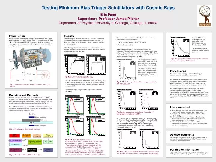
Cosmic Ray Trigger Scintillator Lead bricks MBTS Trigger Scintillator MBTS Counter 3m Optical Fiber PMT (3-in-1 Card) Trigger Summing Card Low Gain 8X Linear Amplifier Differential- to Single- Ended Converter 80m Trigger Cable 5X Attenuator High Gain High Pass Filter(τ ~ 5ms) Signal Pulse Height Analyzer Trigger Cosmic Telescope Testing Minimum Bias Trigger Scintillators with Cosmic Rays Eric FengSupervisor: Professor James PilcherDepartment of Physics, University of Chicago, Chicago, IL 60637 Introduction This project usedcosmic rays to test a prototype Minimum Bias Trigger Scintillator (MBTS) that will be used in the ATLAS experiment at CERN (Fig. 1). The efficiency of the MBTS counter at detecting minimum ionizing particles was characterized. Two separate sections in the MBTS prototype were tested. Results The efficiency of the cosmic telescope was measured as a function of the photomultiplier HV for one trigger counter (Fig. 4a). The PMT high voltage for the other trigger counter was fixed to 1600V for full efficiency. The efficiency of the cosmic telescope was also measured as a function of the relative delay imposed between the signals from the two trigger scintillators (Fig. 4b). • The number of photoelectrons produced per minimum ionizing particle (MIP) was measured to be: • 7.4 for the outer section of the MBTS counter • 10.3 for the inner section. The probability that no charged particles pass through any of the MBTS counters in one bunch crossing is 0.3%. The probability of fewer than three charged particles is 2.25%. A Monte Carlo simulation was performed to simulate the experiment. The predicted energy deposited in the counter is shown in Fig. 6. The predicted number of photoelectrons per MIP is shown in Fig. 7(a,b). The predicted signal shape agrees well with the shape of the measured signalin Fig. 5(b,d). Fig. 9. Charged particle multiplicity expected in the entire region spanned by the MBTS counters. The energy deposition follows a Landau distribution. The mean energy deposited is calculated from the Bethe-Bloch formula. The number of photoelectrons reflects the composition of the Landau distribution for energy deposition with a Poisson distribution for photon statistics. Conclusions The efficiency of a prototype Minimum Bias Trigger Scintillator was measured using cosmic rays. The default (low gain) trigger output of the 3-in-1 electronics card did not provide sufficient signal-to-noise ratio to trigger with full efficiency. Rerouting the trigger output to derive from the high gain output boosted the gain by a factor of 64. The number of photoelectrons produced per MIP and the signal-to-noise ratios for the MBTS counter will be incorporated in the GEANT full simulation in the future. These will be used along with the expected charged multiplicity to set requirements for triggering ATLAS on MBTS signals when the LHC turns on. 88cm 43cm 14cm The 3-in-1 electronics card in the photomultiplier tube reading out the MBTS counter was modified to derive the trigger output from the high gain output instead of the low gain, increasing the signal by a factor of 64. The integrated signal charge from the trigger cable is shown in Fig. 5(a-d). Fig. 4(a,b). Cosmic telescope efficiency. 3.6m 3.6m Fig. 6. Monte Carlo prediction of the energy deposited in the MBTS counter. Fig. 1. Planned deployment of the MBTS counters in the ATLAS detector. Materials and Methods A simple apparatus was built to test the MBTS counter. The MBTS scintillator was laid horizontally on a table, supported by wooden blocks. Two trigger counters sandwiched the MBTS counter and were used as a cosmic telescope to select cosmic rays passing through it (Fig. 2). The MBTS counter was read out with Tile Calorimeter electronics. The signal out of the trigger cable was measured with additional electronics, including a pulse height analyzer (Fig. 3). Literature cited M. Nessi. Minimum Bias Trigger Scintillator Counters (MBTS) For Early ATLAS Running. Technical report, CERN, 2004. S. Eidelman, et al. Review of Particle Physics. Physics Letters B, 592:1+, 2004. D.E. Groom, N.V. Mokhov, and S.I. Striganov. Muon Stopping Power and Range Tables: 10 MeV-100TeV. Atomic Data and Nuclear Data Tables, 78:183–356, 2001. A. Artikov, D. Chokheli, J. Huston, B. Miller, and M. Nessi. Minimum Bias Scintillator Counter Geometry. Technical Report AT-GE-ES-0001, CERN, 2004. Fig. 7(a,b). Monte Carlo prediction of the number of photoelectrons produced per MIP. ATLFast, the fast simulation program for ATLAS, was used to determine the charged particle multiplicity in a single LHC bunch crossing. The charged multiplicity for a section of the MBTS counter is shown in Fig. 8(a-b). The charged multiplicity for the entire region spanned by the MBTS counters is shown in Fig. 9. Fig. 2. Elevation view of the cosmic telescope. Acknowledgments I am grateful to Professor Jim Pilcher for supervising this project. I also thank Kelby Anderson and the rest of the ATLAS group at the University of Chicago for their help. Fig. 5(a-d). Each plot has three spectra: • Scintillator signal (red): This is the signal charge with the photomultiplier HV set to 900V for maximum gain. • Total noise (blue): This is the noise associated with the system, including the TileCal electronics. This noise was measured by turning off the HV to the photomultiplier. • Measurement noise (green): This is the noise introduced by the electronics used to measure the signal out of the trigger cable; it excludes the noise of any Tile Calorimeter electronics. For further information Please contact ejfeng@uchicago.edu. The poster and the final report for this project can be found at http://home.uchicago.edu/~ejfeng/ . Fig. 8(a,b). The charged multiplicity expected in the outer section and the inner section of a counter in a single LHC bunch crossing. Fig. 3. Flow chart of the MBTS readout chain.