Download
1 / 6
90 likes | 627 Views
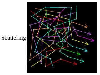
Near Vertical Incident Scattering Antenna. Dr. Carl O Jelinek N6VNG cjelinek@ix.netcom.com. Why use an NVIS antenna?. To work the Skip Zone {out to about 1000 miles}. Areas behind obstructions and in dense foliage. To hear the near in stations just beyond ground wave range.

E N D
Near Vertical Incident Scattering Antenna Dr. Carl O Jelinek N6VNG cjelinek@ix.netcom.com © Dr. Carl O. Jelinek N6VNG
Why use an NVIS antenna? • To work the Skip Zone {out to about 1000 miles}. • Areas behind obstructions and in dense foliage. • To hear the near in stations just beyond ground wave range. • Great for Field Day and contesting as a “Gap Filler” antenna. • Easy antenna for HF mountain topping and camping trips to get RF out of deep canyons. © Dr. Carl O. Jelinek N6VNG
Limitations • Must work frequencies below the Maximum Usable Frequency (MUF). • This is not a DX antenna. • Needs to use an antenna tuner for good match. • Power Limited to about 200 Watts. • Beverage Mode Losses limit achievable gain. © Dr. Carl O. Jelinek N6VNG
NVIS Antenna Dimensions Side A View 38’ 45’ 15’ PVC Mast Rope 38’ 42.5’ SO-239 Side B View PVC CAP 25’ 25’ 45’ 25’ 15’ Top View of feed point 38’ © Dr. Carl O. Jelinek N6VNG
Parts List © Dr. Carl O. Jelinek N6VNG
Construction of NVIS Antenna • Drill PVC Cap to accept SO-239 and 4 screws and nuts • Mount SO-239 to PVC Cap with screw heads down • Cut off the head of a brass screw • Solder a brass screw to center post of SO-239 • Cut antenna wires to length plus a little • Fit one end of each wire with solder lugs • Fit the other with the egg insulators • Install wires to SO-239 using brass nuts and washers {as shown in the figure} • Erect antenna (2 men ~ 5 minutes) • Tune antenna match for minimum VSWR (also could adjust mast height and wire lengths) © Dr. Carl O. Jelinek N6VNG