Download
1 / 34
340 likes | 437 Views
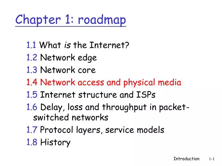
Chapter 1: roadmap. 1.1 What is the Internet? 1.2 Network edge 1.3 Network core 1.4 Network access and physical media 1.5 Internet structure and ISPs 1.6 Delay, loss and throughput in packet-switched networks 1.7 Protocol layers, service models 1.8 History.

E N D
Chapter 1: roadmap 1.1 What is the Internet? 1.2 Network edge 1.3 Network core 1.4 Network access and physical media 1.5 Internet structure and ISPs 1.6 Delay, loss and throughput in packet-switched networks 1.7 Protocol layers, service models 1.8 History Introduction
Q: How to connect end systems to edge router? residential access nets institutional access networks (school, company) mobile access networks Keep in mind: bandwidth (bits per second) of access network? shared or dedicated? Access networks and physical media Introduction
Dialup via modem up to 56Kbps direct access to router (often less) Can’t surf and phone at same time: can’t be “always on” Residential access: point to point access • DSL: digital subscriber line • deployment: telephone company (typically) • up to 1 Mbps upstream (today typically < 256 kbps) • up to 8 Mbps downstream (today typically < 1 Mbps) • dedicated physical line to telephone central office Introduction
HFC: hybrid fiber coaxial asymmetric: up to 30Mbps downstream, 2 Mbps upstream network of cable and fiber attaches homes to ISP router homes share access to router deployment: available via cable TV companies Residential access: cable modems Introduction
Cable Network Architecture: Overview Typically 500 to 5,000 homes cable headend home cable distribution network (simplified) Introduction
Cable Network Architecture: Overview cable headend home cable distribution network (simplified) Introduction
server(s) Cable Network Architecture: Overview cable headend home cable distribution network Introduction
C O N T R O L D A T A D A T A V I D E O V I D E O V I D E O V I D E O V I D E O V I D E O 5 6 7 8 9 1 2 3 4 Channels Cable Network Architecture: Overview FDM: cable headend home cable distribution network Introduction
company/univ local area network (LAN) connects end system to edge router Ethernet: shared or dedicated link connects end system and router 10 Mbs, 100Mbps, Gigabit Ethernet LANs: chapter 5 Company access: local area networks Introduction
shared wireless access network connects end system to router via base station aka “access point” wireless LANs: 802.11b/g (WiFi): 11 or 54 Mbps wider-area wireless access provided by telco operator ~1Mbps over cellular system (EVDO, HSDPA) next up (?): WiMAX (10’s Mbps) over wide area router base station mobile hosts Wireless access networks Introduction
Typical home network components: ADSL or cable modem router/firewall/NAT Ethernet wireless access point Home networks wireless laptops to/from cable headend cable modem router/ firewall wireless access point Ethernet Introduction
Bit: propagates betweentransmitter/rcvr pairs physical link: what lies between transmitter & receiver guided media: signals propagate in solid media: copper, fiber, coax unguided media: signals propagate freely, e.g., radio Twisted Pair (TP) two insulated copper wires Category 3: traditional phone wires, 10 Mbps Ethernet Category 5: 100Mbps Ethernet Physical Media Introduction
Coaxial cable: two concentric copper conductors bidirectional baseband: single channel on cable legacy Ethernet broadband: multiple channel on cable HFC Physical Media: coax, fiber Fiber optic cable: • glass fiber carrying light pulses, each pulse a bit • high-speed operation: • high-speed point-to-point transmission (e.g., 5 Gps) • low error rate: repeaters spaced far apart ; immune to electromagnetic noise Introduction
signal carried in electromagnetic spectrum no physical “wire” bidirectional propagation environment effects: reflection obstruction by objects multi-path fading interference Physical media: radio Radio link types: • terrestrial microwave • e.g. up to 45 Mbps channels • LAN (e.g., Wifi) • 2Mbps, 11Mbps • wide-area (e.g., cellular) • e.g. 3G: hundreds of kbps • satellite • Kbps to 45Mbps channel (or multiple smaller channels) • 270 msec end-end delay Introduction
Chapter 1: roadmap 1.1 What is the Internet? 1.2 Network edge 1.3 Network core 1.4 Network access and physical media 1.5 Internet structure and ISPs 1.6 Delay, loss and throughput in packet-switched networks 1.7 Protocol layers, service models 1.8 History Introduction
roughly hierarchical at center: “tier-1” ISPs (e.g., UUNet, BBN/Genuity, Sprint, AT&T), national/international coverage treat each other as equals Tier-1 providers interconnect (peer) privately Internet structure: network of networks Tier 1 ISP Tier 1 ISP Tier 1 ISP Introduction
Tier-1 ISP: e.g., Sprint Sprint US backbone network Introduction
“Tier-2” ISPs: smaller (often regional) ISPs Connect to one or more tier-1 ISPs, possibly other tier-2 ISPs • Tier-2 ISP pays tier-1 ISP for connectivity to rest of Internet • tier-2 ISP is customer of tier-1 provider Tier-2 ISP Tier-2 ISP Tier-2 ISP Tier-2 ISP Tier-2 ISP Internet structure: network of networks Tier-2 ISPs also peer privately with each other Tier 1 ISP Tier 1 ISP Tier 1 ISP Introduction
“Tier-3” ISPs and local ISPs last hop (“access”) network (closest to end systems) Tier 3 ISP local ISP local ISP local ISP local ISP local ISP local ISP local ISP local ISP Local and tier- 3 ISPs are customers of higher tier ISPs connecting them to rest of Internet Tier-2 ISP Tier-2 ISP Tier-2 ISP Tier-2 ISP Tier-2 ISP Internet structure: network of networks Tier 1 ISP Tier 1 ISP Tier 1 ISP Introduction
a packet passes through many networks! Tier 3 ISP local ISP local ISP local ISP local ISP local ISP local ISP local ISP local ISP Tier-2 ISP Tier-2 ISP Tier-2 ISP Tier-2 ISP Tier-2 ISP Internet structure: network of networks Tier 1 ISP Tier 1 ISP Tier 1 ISP Introduction
Chapter 1: roadmap 1.1 What is the Internet? 1.2 Network edge 1.3 Network core 1.4 Network access and physical media 1.5 Internet structure and ISPs 1.6 Delay, loss and throughput in packet-switched networks 1.7 Protocol layers, service models 1.8 History Introduction
packets queue in router buffers packet arrival rate to link exceeds output link capacity packets queue, wait for turn packet being transmitted (delay) packets queueing (delay) free (available) buffers: arriving packets dropped (loss) if no free buffers How do loss and delay occur? A B Introduction
1. nodal processing: check bit errors determine output link transmission A propagation B nodal processing queueing Four sources of packet delay • 2. queueing • time waiting at output link for transmission • depends on congestion level of router Introduction
3. Transmission delay: R=link bandwidth (bps) L=packet length (bits) time to send bits into link = L/R 4. Propagation delay: d = length of physical link s = propagation speed in medium (~2x10⁸ m/sec) propagation delay = d/s transmission A propagation B nodal processing queueing Delay in packet-switched networks Note: s and R are very different quantities! Introduction
Cars “propagate” at 100 km/hr Toll booth takes 12 sec to service a car (transmission time) car~bit; caravan ~ packet Q: How long until caravan is lined up before 2nd toll booth? Time to “push” entire caravan through toll booth onto highway = 12*10 = 120 sec Time for last car to propagate from 1st to 2nd toll both: 100km/(100km/hr)= 1 hr A: 62 minutes toll booth toll booth Caravan analogy 100 km 100 km ten-car caravan Introduction
Cars now “propagate” at 1000 km/hr Toll booth now takes 1 min to service a car Q:Will cars arrive to 2nd booth before all cars serviced at 1st booth? Yes! After 7 min, 1st car at 2nd booth and 3 cars still at 1st booth. 1st bit of packet can arrive at 2nd router before packet is fully transmitted at 1st router! toll booth toll booth Caravan analogy (more) 100 km 100 km ten-car caravan Introduction
Delay • dproc = processing delay • typically a few microsecs or less • dqueue = queuing delay • depends on congestion • dtrans = transmission delay • = L/R, significant for low-speed links • dprop = propagation delay • a few microsecs to hundreds of msecs Introduction
R=link bandwidth (bps) L=packet length (bits) a=average packet arrival rate Queueing delay (revisited) traffic intensity = La/R • La/R ~ 0: average queueing delay small • La/R -> 1: delays become large • La/R > 1: more “work” arriving than can be serviced, average delay infinite! Introduction
“Real” Internet delays and routes • What do “real” Internet delay & loss look like? • Traceroute program: provides delay measurement from source to router along end-end Internet path towards destination. For all i: • sends three packets that will reach router i on path towards destination • router i will return packets to sender • sender times interval between transmission and reply. 3 probes 3 probes 3 probes Introduction
“Real” Internet delays and routes traceroute: gaia.cs.umass.edu to www.eurecom.fr Three delay measements from gaia.cs.umass.edu to cs-gw.cs.umass.edu 1 cs-gw (128.119.240.254) 1 ms 1 ms 2 ms 2 border1-rt-fa5-1-0.gw.umass.edu (128.119.3.145) 1 ms 1 ms 2 ms 3 cht-vbns.gw.umass.edu (128.119.3.130) 6 ms 5 ms 5 ms 4 jn1-at1-0-0-19.wor.vbns.net (204.147.132.129) 16 ms 11 ms 13 ms 5 jn1-so7-0-0-0.wae.vbns.net (204.147.136.136) 21 ms 18 ms 18 ms 6 abilene-vbns.abilene.ucaid.edu (198.32.11.9) 22 ms 18 ms 22 ms 7 nycm-wash.abilene.ucaid.edu (198.32.8.46) 22 ms 22 ms 22 ms 8 62.40.103.253 (62.40.103.253) 104 ms 109 ms 106 ms 9 de2-1.de1.de.geant.net (62.40.96.129) 109 ms 102 ms 104 ms 10 de.fr1.fr.geant.net (62.40.96.50) 113 ms 121 ms 114 ms 11 renater-gw.fr1.fr.geant.net (62.40.103.54) 112 ms 114 ms 112 ms 12 nio-n2.cssi.renater.fr (193.51.206.13) 111 ms 114 ms 116 ms 13 nice.cssi.renater.fr (195.220.98.102) 123 ms 125 ms 124 ms 14 r3t2-nice.cssi.renater.fr (195.220.98.110) 126 ms 126 ms 124 ms 15 eurecom-valbonne.r3t2.ft.net (193.48.50.54) 135 ms 128 ms 133 ms 16 194.214.211.25 (194.214.211.25) 126 ms 128 ms 126 ms 17 * * * 18 * * * 19 fantasia.eurecom.fr (193.55.113.142) 132 ms 128 ms 136ms trans-oceanic link * means no response (probe lost, router not replying) Introduction
Packet loss • queue (aka buffer) has finite capacity • when packet arrives to full queue, packet is dropped (aka lost) • lost packet may be retransmitted by previous node, by source end system, or not retransmitted at all buffer (waiting area) packet being transmitted A B packet arriving to full bufferis lost Introduction
pipe that can carry fluid at rate Rsbits/sec) pipe that can carry fluid at rate Rcbits/sec) Throughput • throughput: rate (bits/time unit) at which bits transferred between sender/receiver • instantaneous: rate at given point in time • average: rate over long(er) period of time link capacity Rcbits/sec link capacity Rsbits/sec server, with file of F bits to send to client server sends bits (fluid) into pipe Introduction
Rs > RcWhat is average end-end throughput? Rsbits/sec Rcbits/sec Rcbits/sec bottleneck link link on end-end path that constrains end-end throughput Throughput (more) • Rs < RcWhat is average end-end throughput? Rsbits/sec Introduction
Throughput: Internet scenario • per-connection end-end throughput: min(Rc,Rs,R/10) • in practice: Rc or Rs is often bottleneck Rs Rs Rs R Rc Rc Rc 10 connections (fairly) share backbone bottleneck link Rbits/sec Introduction