Download
1 / 31
310 likes | 429 Views
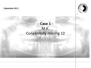
Replacing a Congenitally Missing Lateral Incisor using the Skinny 2.4. The case is a 23 year old petite female. The patient was congenitally missing the maxillary left lateral incisor. Not the diminutive bone volume. Preoperative panoramic radiograph of the edentulous space.

E N D
Replacing a Congenitally Missing Lateral Incisor using the Skinny 2.4 The case is a 23 year old petite female .
The patient was congenitally missing the maxillary left lateral incisor. Not the diminutive bone volume.
Because of the diminutive bone volume and palpable undercuts, a minimal flap was reflected to directly visualize the labial and palatal osseous contours.
The first step in the drilling sequence is the Locator Drill.
The Locator Drill is has a maximum cutting diameter of 1.8mm with the depth marking at 8mm.
The Locator is important in a skilled implant placement because it establishes the center of the osteotomy which places the implant. It also begins the trajectory of the osteotomy.
The Final Sizing Drill for the Skinny 2.4 System is sized for the length of implant selected. It has a 2.4mm diameter cutting diameter and a built in countersink. This offers safety and efficiency during the surgical phase.
Notice the countersink in the osteotomy that is matched in diameter and depth to the implant.
The Skinny 2.4 is delivered to the osteotomy via the vial cap driver system. This is a true premounted delivery system that permits seamless insertion of the implant from the sterile vial to the osteotomy.
The implant is threaded digitally with the vial cap as far as the practitioner desires. Depending on the density of the bone, the implant can be threaded as much or as little as is comfortable.
The vial cap is removed from the driver exposing the 4mm square drive male end. Several instruments can be utilized to thread the implant in to full depth. A ratchet wrench, a straight driver, or an internal 2mm hex within the access opening of the driver can be used.
The implant is threaded digitally with the vial cap as far as the practitioner desires. Depending on the density of the bone, the implant can be threaded as much or as little as is comfortable.
Notice the final threaded depth of the implant corresponds to the depth of the Final Sizing Drill.
The horizontal line indicator on the Final Sizing Drill exactly places the coronal aspect of the implant with predictability, efficiency and safety. Notice the final threaded depth of the implant corresponds to the depth of the Final Sizing Drill.
When the green driver is removed, the precision of the osteotomy and the important crestal ridge relative to the coronal aspect of the implant is apparent.
The first stage surgical cover screw is threaded into the Skinny via its premounted .050” (1.25mm) hex driver.
After three months has passed, the implant is exposed and the first stage surgical cover screw is replaced with a tissue healing abutment and the site is allowed to heal.
The green driver that was used at the time of surgery is used again as an impression coping to create an implant level master model.
The green driver is seated and positively mated to the implant and secured via a .050” (1.25mm) hex drive fixation screw. The driver is the same one used at surgery to deliver and thread the first stage surgical cover screw to the implant.
The vial cap driver is removed and the case is ready for conventional crown and bridge impression techniques. Notice that the flat of the green driver is facing facially to make it easier to re-insert it into the impression.
Crown and bridge impression techniques and materials employed. If the impression coping had interfered with the bite, the impression would be taken and the bite would be confirmed after the impression coping was removed.
Whatever technique and material is employed is acceptable. This impression will not require the accuracy of the final impression. This impression is to customize an abutment.
In this case, the impression coping did not interfere with the bite, so the impression captured the impression coping, the counter arch and the bite.
In this case, the impression coping did not interfere with the bite, so the impression captured the impression coping, the counter arch and the bite.
A custom milled Cement On Abutment was threaded to full seat on the implant and a conventional crown and bridge impression was taken to construct the final crown.