Download
1 / 23
230 likes | 355 Views
ISG9 December 10 – 13 2002. Backgrounds in the NLC BDS. Takashi Maruyama SLAC. Major source of detector background: Halo particles hitting beamline components generate muons and low energy particles. Halo particles generate sync. radiations that hit VXD.

E N D
ISG9 December 10 – 13 2002 Backgrounds in the NLC BDS Takashi Maruyama SLAC
Major source of detector background: Halo particles hitting beamline components generate muons and low energy particles. Halo particles generate sync. radiations that hit VXD. Beam-gas scattering generates low energy particles. Collimate Halo particles: Spoilers and Absorbers Collimation depth – (nxsx, nysy) Reduce halo size using Octupoles What is Halo, and How much: Drozhdin’s 1/x-1/y model Flat distribution with 50sx,50sx’,200sy,200sy’,3%DE/E Pencil beam hitting SP1 Calculated halo ~10-6, but design collimation for 10-3. Background and collimation
2001 Collimation System & FF integrated design Octupole Doublets FD A Final Focus Final Focuscollimation IP A Energy collimation FD Betatroncollimation A IP FD IP FD IP S SA SA SA A New scheme of the Collimation Section and Final Focus with ODs
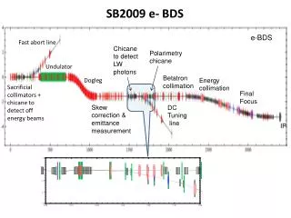
NLC Beam Delivery Section in Geant 3 IP TRANSPORT lattice FF Collimators Magnets (bands,quads, sexts, octs) sp3 sp5 a3 a5 location, orientation, length, field strength, aperture 295 cm sp2 sp4 E-slit a2 a4 sp1 Spoilers and Absorbers Geant 3 1480 m
Muon Backgrounds from Halo CollimatorsNo Big Bend, Latest Collimation & Short FF FF Energy 18m & 9m Magnetized steel spoilers Betatron BetatronCleanup If Halo = 10-6, no need to do anything If Halo = 10-3 and experiment requires <1 muon per 1012 e- add magnetized tunnel filling shielding Reality probably in between
250 GeV/beam Muon Endcap Background Bunch Train =1012 Engineer for 10-3 Halo Calculated Halo is 10-6 Collimation Efficiency 105
LCD Detector in GEANT3/FLUKA GEANT3: e+/e- and g backgrounds FLUKA: Neutrons
NLC Detector Masking Plan View w 20mrad X-angle LD – 3 Tesla SD – 5 Tesla R=1 cm 32 mrad 30 mrad Apertures: 1 cm beampipe at the IP 1 cm at Z = -350 cm
VXD Hits from 250 GeV e- hitting QD0 QD0 e-, e+ 250 GeV e- z
Synchrotron radiations quads Photons from quads bends FF doublet aperture 1 cm Photons from bends
cm Sync. Radiation vs. IP • Track particle with n• backward from IP to AB10. • Track particle to IP and generate sync. radiations. Find sync. radiation edge as a function of (nx, ny). nx = 18.5 x+, 17.2 x- ny = 50.9 y Find AB10 and AB9 apertures as a function of (nx, ny) xIP nx yIP ny
Sync. radiation at z = -350 cm Apertures at AB10 & AB9 nx = 16.2 x+ nx = 16.8 x- AB9 AB10 x x nx nx ny = 41.6 y AB10 AB9 y y ny ny
Spoiler/Absorber Scattering Spoilers/Absorbers Settings for NO OCT Half apertures sx sy X Y (um) * TRC 6500 3900 8000 * * ESP 0.5 X0 ~x5 beamloss * Sp1 ~ SP4 settings with OCT x2.5
Synchrotron Radiation and Collimation Depth Criteria: No photons hit R > 1 cm at 1) z = 0 cm or 2) z = 350 cm 1) x’ < 570 rad = 19 x 30.3 rad y’ < 1420 rad = 52 x 27.3 rad 2) x’ < 520 rad = 17 x 30.3 rad Y’ < 1120 rad = 41 x 27.3 rad x y
10-5 Halo Model X’ Y’ X (cm) Y (cm) • 1/x and 1/y density over Ax = (6 – 16)x and Ay = (24 – 73)y • E/E = 1% (Gaussian) • Halo rate 10-3 y (cm) x (cm)
Particle loss distribution OCT-OFF ESP 42% to IP EAB AB7 OCT-ON 82% to IP AB10 DP2 Z (m)
Particle distributions at FF absorbers. AB7 AB9 AB10 DP1 DP2 y is OK, but x is tight.
Sync. Radiations at IP Quad Ng=7.3 Ne- <Eg>=4.8 MeV Bend Log10(E) (GeV) Y Hit 1 cm X (cm) X (cm)
42% to IP FLAT Halo 50sx,50sx’,200sy,200sy’,3%DE/E OCT-OFF 1/x – 1/y ESP 42% to IP EAB AB10 AB7 FLAT 0.6% to IP Z (m)
Transmission rate through E-slit and beam-loss in FF Pencil beam hitting SP1 OCT-ON OCT-OFF
Summary • NLC BDS and collimation system are studied using Geant 3. • FF absorbers are set so that no sync. radiations hit the detector apertures. • Assuming 10-3 halo, the particle loss is < 10-8 in FF and the muon background is tolerable. • Octuples allow x2.5 looser spoiler settings. • OCT-OFF settings are well optimized, but OCT-ON settings need further optimization.