Download
1 / 8
80 likes | 185 Views
The Tracker Dry Gas system was initially designed as a standalone unit meant to be operated through manual and pneumatically driven valves. The selection criterion for the gas source was based on the available gas pressure and

E N D
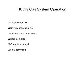
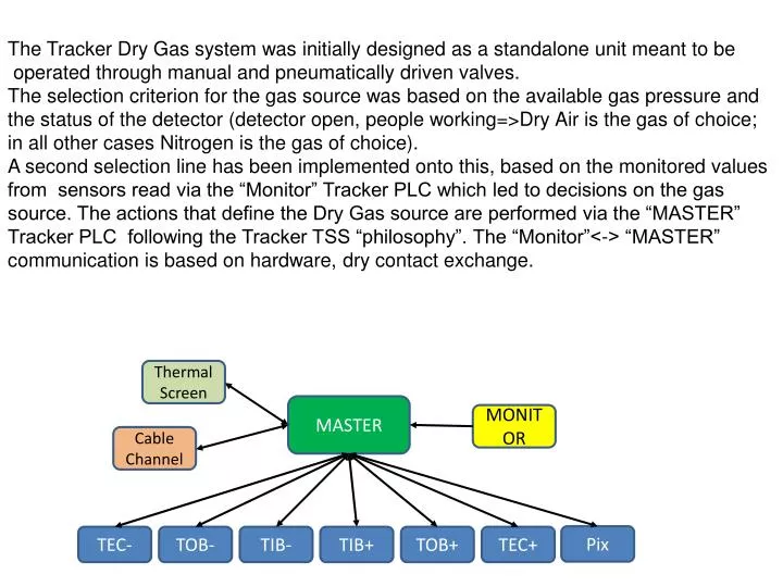
The Tracker Dry Gas system was initially designed as a standalone unit meant to be operated through manual and pneumatically driven valves. The selection criterion for the gas source was based on the available gas pressure and the status of the detector (detector open, people working=>Dry Air is the gas of choice; in all other cases Nitrogen is the gas of choice). A second selection line has been implemented onto this, based on the monitored values from sensors read via the “Monitor” Tracker PLC which led to decisions on the gas source. The actions that define the Dry Gas source are performed via the “MASTER” Tracker PLC following the Tracker TSS “philosophy”. The “Monitor”<-> “MASTER” communication is based on hardware, dry contact exchange. Thermal Screen MASTER MONITOR Cable Channel Pix TEC- TOB- TIB- TIB+ TOB+ TEC+
Enabled dry gas, enabled dryer Enable dry gas, enable dryer To Gas Room
Monitor Analog Inputs • The Monitor currently checks and issues directions to the Master: • Two Dew Point temperatures in what should be the ones of the dry gas flowing to the Tracker; dew-point limits set to -45 0C for N2 and -15 0 C for Dry Air. • It additionally reads Analogue values: • One Dew Point temperature at the output of the Air Dryer (limited to >= -65 Celsius); • The total dry gas Flow to the Tracker (limit set to 12m3/hr ) ; • The Pressure in the Air Dryer line; • The Pressure in the Air Bottles line – broken. • The Pressure in the Dry Air line to the Trimatic; These pressure meters are not maintainable; when we change the one in the air bottles we change them all.
Dryer Electrovalve Trimaticindicators in the horizontal direction= N2, vertical=Dry Air Dew-point meter #3 N2 Electrovalve
Monitor Digital Inputs • The Monitor reads Digital states: • The Open/Closed status of the pressure-actuated valve on the Nitrogen line (1 bit); • The Open/Closed status of the pressure-actuated valve on the Dry Air line (1 bit); • The Open/Closed status of the pressure-actuated valve on the Air Dryer to Dry Air line (1 bit); • The Open/Closed status of the pressure-actuated valve on the Air Bottles to Dry Air line (1bit, broken, to be changed);
Dryer When going back from bottles or from Dryer, the red pushbuttons have to be used, then no MASTER Acknowledge needed; pressure-drivenaction Push-buttons • Bottles Dry Air source switchboard When going back from dew-point dry gas source change a MASTER Acknowledge needed; MASTER-driven action • Master acknowledge
Master Digital Outputs • The Master, on the basis of two Digital lines from the Monitor, currently controls: • One electro-pneumatic valve on the Nitrogen line (Request Nitrogen Enable to allow flow); • One electro-pneumatic valve on the Air Dryer to Dry Air line (Request Dryer Enable to allow flow); • In case of out-of-limits dew point measurement or flow, the Master sends the request to go to warm to the Cooling plants, as well as changes the Dry Air source. This is not a topic of the current meeting, however the implementation and procedure has been tessted thoroughly.
The changes of the Dry Panel – Dry bottle switch and the change of the pressure gauges are important and should be carefully scheduled since both the gas group and the TSS group have to test and work together. The coming interventions, in July, are by far less intrusive and have to do with the Dry Gas source for the cold boxes. However, they will still be performed together since we would like to avoid any disruption to the cooling plant operation. We should plan on a “meeting of experts…Andrea, PGV, machi” on the 15th for Preparing the action list and the software changes during the intervention if any will be needed.