Download
1 / 41
410 likes | 517 Views
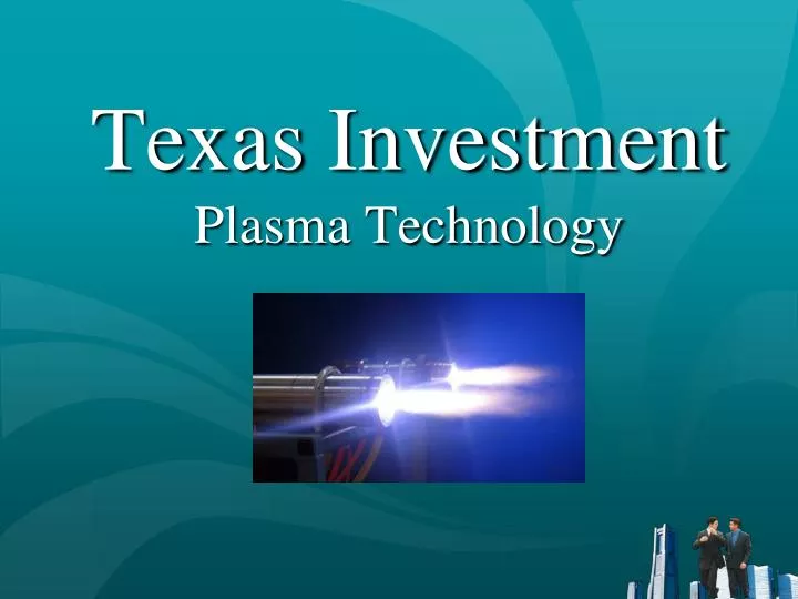
Texas Investment Plasma Technology. Achieving “Zero Waste” with Plasma Arc Technology. Texas Investment 3025 Country Club Dr. Pearland, TX 77581 Telephone: 281-389-0771. Website: www.texas-investment.com E-Mail: info@texas-investment.com. Achieving “Zero Waste”.

E N D
Achieving “Zero Waste”withPlasma Arc Technology Texas Investment 3025 Country Club Dr. Pearland, TX 77581 Telephone: 281-389-0771. Website: www.texas-investment.com E-Mail: info@texas-investment.com
Achieving “Zero Waste” Plasma arc technology offers a unique opportunity to achieve the “zero waste” goal by providing the capability to eliminate the need for land disposal of many hazardous wastes and to recover energy from municipal solid wastes and other organic wastes while producing salable byproducts and eliminating requirements for landfilling of ash or other residual materials.
What is PLASMA? “Fourth State” of matter Ionized gas at high temperature capable of conducting electrical current Lightning is an example from nature
Non-transferred arc plasma torch In a plasma arc torch, the plasma gas serves as a resistive heating element to convert electricity into heat. Because it is a gas and cannot melt, temperatures in excess of 7000°C can be produced.
Characteristics of Plasma Arc Technology Plasma acts as a resistive heating element that cannot melt and fail Produces temperatures of 4,000°C to over 7,000°C Torch power levels from 100kW to 200 MW produce high energy densities (up to 100 MW/m3) Torch operates with most gases – not a combustion process Elimination of requirement for combustion air : Reduces gas volume requiring treatment Reduces potential for formation of complex organics (i.e., dioxins and furans)
Plasma arc technology is ideally suited for waste treatment Hazardous & toxic compounds broken down to elemental constituents by high temperatures Organic materials Pyrolyzed or volatilized May be converted to fuel gases Amenable to conventional off-gas treatment Residual materials (radionuclides, heavy metals, etc.) immobilized in a rock-like vitrified mass which is highly resistant to leaching
Plasma arc technology remediation experience Heavy metals Radioactive wastes Industrial sludges Municipal solid waste Electric arc furnace dust Liquid/solid organic wastes PCB’s Asbestos Chemical wastes Medical wastes Plastics Used tires
Waste Processing Applications ofPlasma Arc Technology Waste Destruction Energy/Material Recovery
Waste Destruction Applications Melting and vitrification of inorganic materials Pyrolysis of organic materials Molten metal or glass bath provides heat transfer Heat causes breakdown of complex materials into elemental components Rapid quenching prevents complex compound formation (dioxins and furans) Water gas shift reaction to remove carbon C + H2O → H2 + CO Gaseous products are fuel and simple acid gases Vitreous residue is resistant to leaching – suitable for aggregate
Recent Commercial Applications Mixed waste treatment facility-Richland, WA Allied Technology Group (ATG) Medical waste vitrification facility-Honolulu, HI Asia Pacific Environmental Technologies (APET) Incinerator ash vitrification facilities – Europe and Japan Europlasma IHI Inc./Westinghouse Plasma
Recent DoD Plasma Furnace Applications Plasma Arc Shipboard Waste Destruction System (PAWDS) U.S. Navy Warships (NSWCCD) Plasma Arc Hazardous Waste Treatment System (PAHWTS) U.S. Naval Base, Norfolk, VA (Office of Naval Research, Environmentally Sound Ships Program) Plasma Ordnance Demilitarization System (PODS) Naval Surface Warfare Center, Crane, IN (Defense Ammunition Center)
Recent DoD Plasma Furnace Applications – cont’d Plasma Waste Treatment System (Pyrotechnics and Energetics) Hawthorne Army Ammunition Plant, NV (Armament Research and Development Engineering Center) Plasma Energy Pyrolysis System (PEPS) Demonstration Facility (Medical Waste and Blast Media), Lorton, VA U.S. Army Construction Engineering Research Laboratories (CERL) Mobile PEPS Demonstration System, U. S. Army CERL
GaTech Plasma Waste Processing & Demonstration System Developed by USACERL Congressional funding Capacity 10 tons/day Complete system Feed & Tapping Furnace Emissions control Wastewater treatment 1MW mobile generator
Plasma Processing for Energy and Materials Recovery Research on waste destruction noted that pyrolysis produced useful fuel gases and inert residuals from organic wastes including MSW. Relatively high plasma energy requirements (~600 kWh/ton) and capital cost of complex molten bath reactors limited economic feasibility of pyrolysis processes. Use of gasification technology has made plasma a more economically attractive alternative.
Plasma Pyrolysis of MSW SteamNegligible Gas Heat Energy1.05 MBtu Losses1.77 MBtu PLASMA GASIFIER MSW1 Ton – 9.39 Mbtu33% Moisture Electricity0.56 MWHr – 1.90 MBtu Gas Heating Value OutputElectricity Input = 4.30 Product Gas30,300 SCFHeating Value = 8.16 MBTU Based on data from Resorption Canada, Ltd. 1995(Summarized and converted to English units)
Hitachi Metals Plasma MSW System – Japan CokeandLimestone Excess Heat Utilization & Power Generation Plasma Torch Metal Slag
Hitachi MetalsUtashinai, Japan Plant Commercial 200 ton/day plasma processing system Designed for Municipal Solid Waste (MSW) and Automobile Shredder Residue (ASR). Represents MSW from approximately 30,000 US households Plant has two plasma reactors. Four 300 kW torches (Westinghouse Plasma Corp.) per reactor Each reactor will process ~4 tons/hr Generates 7.9 MW of electricity (4.3 MW to grid) Could supply 4,000 US households with electricity (up to 15% of households supplying waste to the system). Fully operational in April 2003.
Plasma Gasification: MSW Waste-To-Energy U.S. Projects Under Development St. Lucie County, FL: 3,000 TPD Tallahassee, FL: 1,000 TPD New Orleans, LA: 2,500 TPD International Falls, MN: 150 TPD Sacramento, CA: 1,000 TPD State of Hawaii, Location: TBD: 300 TPD
Plasma Gasification MSW Waste-To-Energy Projects Under Development City of Manila, P.I. -- 4,000 TPD in 500 TPD Units. Cebu City, P.I. – 3,500 TPD in 500 TPD Units. Clark Field, P.I. -- 4,000 TPD in 500 TPD Units. Tangshan, PRI –3,500 TPD in 500 TPD Units. Mexico City, Mexico -- 3,500 TPD in 500 TPD Units. Sydney, Australia – 3,500 TPD in 500 TPD Units.
Texas Municipal Locations Suited for Plasma Gasification MSW Waste-To-Energy Projects Houston, Texas -- 2,000 TPD in 500 TPD Units. Corpus Christi, Texas – 3,500 TPD in 500 TPD Units. Dallas, Texas -- 4,000 TPD in 500 TPD Units. Austin, Texas –3,000 TPD in 500 TPD Units. Galveston County, Texas – 2,000 TPD.
PLASMA PROCESSING OF MSW AT COAL-FIRED POWER PLANTS Concept • Collocate MSW plasma processing plants (in modules of 1,000 TPD) with existing operational coal-fired power plants. • The amount of coal supplied to a plant will be reduced, proportionate to the thermal output of the MSW plant. • The hot gaseous emissions from the plasma plant afterburner system will be fed directly into the coal plant combustion chamber to supplement the combusted coal gases. • The combined plasma and coal gaseous emissions would produce steam and power equal to the normal coal plant generating capacity. • MSW would replace large volumes of coal for power generation in a very efficient, cost-effective and environmentally cleaner operation.
PLASMA PROCESSING OF MSW AT COAL-FIRED POWER PLANTS Reduced Capital Costs of MSW Plant(1) • Use existing power plant facilities – Steam generation system – Off gas treatment system – Electrical generating system • Use existing transportation network • Build on power plant land, if feasible (1) Geoplasma, LLC estimated costs
PLASMA PROCESSING OF MSW AT COAL-FIRED POWER PLANTS Summary By 2020, if all MSW was processed by plasma at coal-fired power plants (1 million TPD), MSW could: • Supply about 5% of U.S. electricity needs • Replace about 140 million TPY of coal • Eliminate about 15 million TPY of coal ash going to landfills • Provide significantly cleaner coal plant air emissions • Support the goals of the Clear Skies Act
YEAR 2020SELECTED RENEWABLE ENERGY SOURCES Source Quads (1015 BTU) Plasma Processed MSW(1) 0.90 Geothermal(2) 0.47 Landfill Gas(2) 0.12 Solar(2) 0.09 Wind(2) 0.04 _____________________ Assumes 1 million TPD Extrapolated from 1999 statistics
Capital Costs: Incineration vs Plasma Gasification Facilities (Note: Plasma Costs are Geoplasma LLC Estimates)
Potential DoD Applications Processing of hazardous wastes Major installations Industrial activities (depots, Air Force Plants) “Bare Base” and “Zero Footprint” Operations Process solid and sanitary wastes Eliminate landfill or shipping of residuals Recovery of energy as steam or hot water
Goals for the international implementation of our Plasma Arc Technology Construction of “Model” Plasma sites in the U.S., and key countries such as Mexico, Brazil, Argentina and Chile. Securing U.S. and foreign regulatory acceptance and permitting. Media programming, geared to inform the public of the potential of Plasma.