Download
1 / 27
270 likes | 380 Views
ME 441 Senior Design. CUA Hovercraft – Class of 2008-2009. ME 441 Semester Summary 12/4/08. Joe Cochrane, Aldo Glean, James McMahon, Omar Monterrubio, Kalin Petersen. Presentation Outline. Project purpose System requirements Hull and deck Lift calculations Skirt construction

E N D
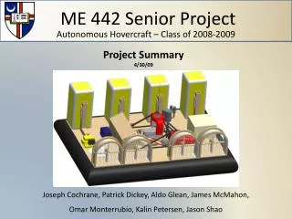
ME 441 Senior Design CUA Hovercraft – Class of 2008-2009 ME 441 Semester Summary 12/4/08 Joe Cochrane, Aldo Glean, James McMahon, Omar Monterrubio, Kalin Petersen
Presentation Outline • Project purpose • System requirements • Hull and deck • Lift calculations • Skirt construction • Lift engine modifications/mount • Lift fan justification • Thruster justification/testing • Thruster housing design • 36 V Power system/alternator testing • Goals for next semester
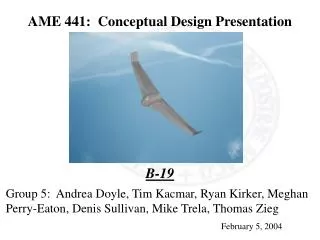
Purpose To develop an autonomous hovercraft for carrying landmine detection hardware for the facilitation of humanitarian efforts to de-arm post conflict mine fields.
System Requirements • Sufficient deck space to accommodate components • Cushion pressure less than 8 psi (pressure required to trigger a landmine) • Remote maneuverability • Minimum payload capacity: ~562 lb - Does not include weight of hull or possible counter-balance weight
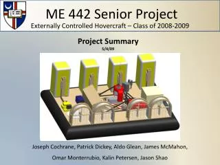
Hull and Deck • Equipment requirements: • Minimum area: ~50 ft2 • Does not include obscure equipment footprints or additional equipment • Radar antenna spacing • Modeled deck layout • Proposed size: 7’x10’ 7’x10’ Deck Size* 6’x10’ Deck Size* *configurations are tentative
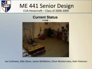
Hull and Deck • Hull is ~3x bigger than last year’s, but conceptual design was retained • Proven design • Simplicity • Time and money invested • Took approximately 6 weeks to complete construction • Next semester: • Waterproofing: drain holes and polyurethane
Hull: I-beam Testing • Conducted “pullout test” on sections of base to I-beam and deck to I-beam connections • Test shows connections can withstand over 15 psi • Connections must be able to withstand at least 7.7 psi • Factor of safety of at least 1.94 Calculations
Lift Calculations • Fluid dynamics reexamined for the lift system • Cushion pressure: 0.065 psi • Required flow rate: 4010.6 cfm • Inside hull pressure: ~0.72 psi Calculations
Skirt • Maintained previous skirt design • Used same material (ballistic nylon) • Went to Cambridge Canvas & Sail Loft in Cambridge, MD to have skirt professionally sewn
Lift Engine • Zenoa G50 Fan Cooled Engine • 45 hp @ 5800 rpm • 2 stroke, Twin Cylinder, Horizontal Opposed • Engine reorientation required intake manifold modifications • Intake manifold modifications are complete • Engine fully functional in new orientation • Next semester: • Exhaust modifications • Engine shaft-lift fan-alternator connection • Engine mount
Lift Engine Modification Original
Conceptual Engine Mount Design • Top views • Side view
Lift Fan • Previous lift fan model and size determined sufficient for project requirements
Thrusters During the summer, gas engine was tested extensively Decision was made to switch to electric motors due to difficulty with tuning and inconsistency of gas engine Researched electric model airplane motors, went with largest model
Thrusters • Electrifly Rimfire 63mm Out-Runner Brushless Motor • Weight: 22.4 oz. (635 g) • Suggested prop size: 18x6W - 20x8E • Input Voltage: 29.6-37 V
Thruster Testing • Wooden 20x8 (diameter x pitch) and plastic 20x8 propellers tested • Concluded that the wooden and plastic props produced the same amount of thrust force • Plastic props were chosen: less expensive
Thruster Housing • Electric motor is lighter and smaller • Thruster housing design modified for space conservation • Decision to use 0.01” thick galvanized steel for thruster shroud in place of bending wood • Next semester: • Motor mount strength testing • Thrust reduction testing
36 V Power System • 250 Amp externally regulated alternators • 36V system using alternators to power electric motors • Basic testing completed
Alternator Testing • 28.9 V produced on unloaded alternator at approximately 3300 rpm • Tested electric motor powered by single alternator • Motor was run successfully, but only produced maximum of 12.6 lb of thrust
Goals for Next Semester • Final engine mount design and construction • Working hovercraft • Functioning 36 V power system • Thruster controls • Employment of radar, GPS and other system components
Questions? For more information: http://students.cua.edu/51mcmahon/