Download
1 / 23
500 likes | 2.04k Views
Steam Engine. Applied Thermodynamics & Heat Engines. MOAZ HASSAN (Lecturer) Mechanical Engineering Department University of Lahore. Applied Thermodynamics & Heat Engines. Where Steam Engine/Turbine Stands. Steam Engine is an External Combustion Engine, used to Produce Electricity.

E N D
Steam Engine Applied Thermodynamics & Heat Engines MOAZ HASSAN (Lecturer) Mechanical Engineering Department University of Lahore Applied Thermodynamics & Heat Engines
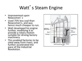
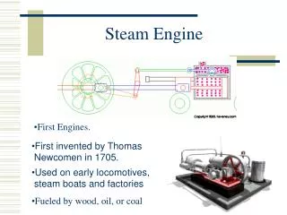
Where Steam Engine/Turbine Stands • Steam Engine is an External Combustion Engine, used to Produce Electricity.
Steam Engine • In a modern piston steam engine, steam from the boiler enters a thick-walled metal chamber called a steam chest. MOAZ HASSAN
Construction • Steam Engine are Double Acting i.e. It consists of a cylinder in which a double-acting piston operates. Double-acting means that both back and front faces of the piston are arranged to be working faces. • Thus, when one piston face is working, the other piston face is exhausting. • On the return stroke, what was the exhausting face now becomes the working face, and what was the working face now becomes the exhausting face. • In this way there are two working strokes per revolution. MOAZ HASSAN
Construction • The external end of the piston rod is connected to a Crosshead. This crosshead reciprocates in guides and supports the piston rod end. The small end of the connecting-rod is connected to the crosshead. The reciprocating motion of the piston is thus transmitted, via the crosshead, to the Connecting-Rod. • The big end of the connecting-rod is connected to the crank which turns on the crankshaft that runs in the main bearings. A Flywheel is fitted to the crankshaft. • Control of the steam to and from the cylinder is by means of a Valve which is assembled in the valve chest mounted on the side of the cylinder. These are also called Piston Valves. MOAZ HASSAN
Construction • A common way of operating this valve is to use an eccentric mounted on the crankshaft. The reciprocating motion of the eccentric is transmitted to the valve by a valve operating link called the Eccentric Rod. • In order to reduced condensation loss, the cylinder is often surrounded by a Steam Jacket. High-pressure steam from the main is fed to this steam jacket, which thus helps to maintain a high general cylinder temperature and cuts down working steam condensation loss. Condensate from the jacket is drained through a steam trap. • Note the Governor fitted to the end of the crankshaft. The governor is connected via a linkage up to the governor valve. The governor serves to maintain nearly constant engine speed at all loads up to full load. MOAZ HASSAN
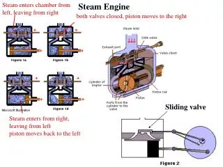
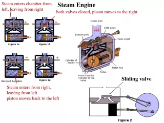
Working Principle • The Steam Engine Valve • In a modern piston steam engine, steam from the boiler enters a thick-walled metal chamber called a steam chest. • There are three holes, or ports. The centre port opens into a pipe, the steam outlet or exhaust; the other two ports, one on either side of the centre port, open into another thick-walled metal chamber, the cylinder. • This is the D-slide valve, which always covers the steam outlet port and alternately covers one of the two intake ports. MOAZ HASSAN
Working Principle • Working Method • Steam from the boiler rushing through one of the intake ports strikes one side of the piston and forces it towards the opposite end of the cylinder. The movement of the piston is called a stroke. • As the piston moves, the D-slide also moves so that, when the piston reaches the end of its stroke, the port through which the steam entered the cylinder is closed. MOAZ HASSAN
Working Principle • Working Method (Continued….) • At the same moment, the D-slide valve opens the other port so that incoming steam is guided to the other side of the piston. • Steam striking this side pushes the piston back towards the opposite end of the cylinder. • As the D-slide valve allows steam to enter alternately one intake port and then the other, this valve also keeps open a channel to the steam outlet, where the steam that has just finished pushing the piston escapes. • There the steam is cooled and condenses into water, which may be sent back to the boiler where it is again heated into steam. Exhaust pressure of Steam is also called Back Pressure. • The process of steamentering and escape of steam first from one side of the piston and then the other, goes on continually as long as steam enters the chest at pressure that is high enough. MOAZ HASSAN
Hypothetical Steam Engine Indicator Diagram • The hypothetical indicator diagram for a single cycle of a steam engine is shown in Fig. 11.4. Clearance has been neglected. • The cycle operations is • 1—2 At point I some steam is admitted to the cylinder; this continues until point 2 is reached, where the steam is cut off. Point 1 is point of admission. MOAZ HASSAN
Hypothetical Steam Engine Indicator Diagram • The Cycle Operations (Continued…..) • Now the ratio V3/V2 is often written r. called the expansion ratio or the number of expansions. Thus • The mean effective pressure of the cycle can now be obtained as, MOAZ HASSAN
Diagram Factor • The Actual Steam Engine Diagram is different from theoretical Diagram due to losses. Comparison of Actual & theoretical Diagram is follow, • In Steam Engine Clearance Vol. is 1/10-1/50. • For max. Pressure build up, Steam Admission is opened before the Piston reaches IDC. • At Admission, Pressure is low to Steam Losses Main & throttling valve. • Continuously Steam Loss through the Valve causes the Damage like grooves on Valve’s edges, is called Wire Drawing. • Upon admission, the working steam will meet working surfaces which are at a lower temperature. thus some steam will condense on these surfaces. There is no corresponding increase in work output for this increased steam supply, so the thermal efficiency tends to be reduced. MOAZ HASSAN
Diagram Factor • Comparison of Actual & theoretical Diagram (Continued….) • Due to the lower admission pressure, the expansion line will be lower than the theoretical expansion line due to condensation on the cylinder wall. • During Exhaust stroke , Actual Pressure is slightly higher in theoretical diagram. Because high temperature & pressure may stay there due to condensation. • At Compression, some steam is locked in cylinder (called Cushion Steam) to reduce Steam Consumption. • Actual Area is Smaller as compare to theoretical Area of Diagram. So • Diagram Factor = K =Theoretical DiagramArea/ActualDiagramArea Similarly, • Diagram Factor = K =Theoretical Work Done/ActualWork Done • Diagram Factor = K =Theoretical Mean Eff. Prr./ActualMean Eff. Prr. MOAZ HASSAN
Steam Engine Governing • A steam engine must be capable of taking up or shedding load • If load is increased then more work must be done in the cylinder. • If load is decreased then less work must be done in the cylinder. • So there are two ways as follow, • A) Throttle governing • control the engine output by varying the intake pressure to the engine. • The throttling of the steam is usually taken care of using a valve controlled by a governor on the engine. • Due to the constant cut-off, large quantities of steam are used, as much at low loads as at high loads MOAZ HASSAN
Steam Engine Governing • Cut-off governing • Method of controlling the output of the engine by varying the cut-off. The intake steam pressure now remains constant. • No Steam Consumption. It is more efficient. • Throttle governing and Willan’s line • Linear relationship exists between the steam consumption and the indicated power Output. • The indicated power is zero at B. so B represents loss due to condensation, leakage. MOAZ HASSAN
Indicator Diagram for Double-Acting • Now when thc head end is carrying out its working stroke, for the same piston direction, the crank end is exhausting. Also, when the head end is exhausting, the crank end is carrying out its working stroke • Work done per revolution is the sum of the diagram areas taken separately. MOAZ HASSAN
The Compound Steam Engine • In Single Cylinder following Reasons Problems can occur: • To accommodate high Pressure & large Volume Expansion, heavier reciprocating masses required that result in unbalancing. • A heavy flywheel will be required for smooth Operation. • Higher temperature difference result in Condensation Loss. • Multi-cylinder Engine is preferred over Single Cylinder Engine because • The steam partially expanded in high-pressure cylinder then moves to next cylinder. Cylinder with high-pressure steam need not have such a large volume, so it can have lighter construction. • Steam Exhausted from 1st Cylinder has larger volume & low Pressure. So larger Cylinder Volume is required but with Lighter Construction. • In each cylinder there will be a lower overall temperature range, so condensation loss is reduced. MOAZ HASSAN
The Compound Steam Engine • Multi-cylinder Engine over Single Cylinder (Cont…) • In two or more cylinders with Lighter Construction & a suitable crank arrangement. it is possible to obtain better balancing than with a single cylinder. These result in a smoother torque output. • Note : • A receiver is fitted between cylinders to hold the steam until the following cylinder is ready for it. • As the strokes of the cylinders of a compound engine are generally made equal .To accommodate the larger steam volumes, the diameters of the following cylinders are made larger. • Double-Expansion Engine have two Cylinder, 1st Cylinder is High Pressure & 2nd cylinder is Low Pressure Cylinder. • Triple-Expansion Engine have three cylinder, cylinders are called the High-pressure, Intermediate-pressure and Low-pressure cylinders MOAZ HASSAN
The Compound Steam Engine • Hypothetical Diagram for Compound Engine • High Pressure cylinder diagram is 1276 • Low Pressure cylinder diagram is 76345 • Expansion is Hyperbolic i.e. PV=C • Area 4-5 is larger than 6-7 to accommodate the Steam. • HP cylinder volume is equal to cut-off volume of Low pressure cylinder. • In Low Pressure Cylinder, Steam releases earlier i.e. at point 3 instead of point 4’. Because Cylinder Volume is more but it does not compensate for complete Expansion/Work. • Two Diagrams fitted together, but they are quite different. MOAZ HASSAN
The Compound Steam Engine • Equal Initial Piston Loads • In double acting, for two Cylinder, Net Pressure = P1 – P7 (For HighPressure Cylinder) Net Pressure = P7 – P5 (For Low Pressure Cylinder) Force = Pressure * Area For Equal Initial Piston Loads, FHP = FLP Then (P1 – P7)AHP = (P7 – P5)ALP Where, AHP = Area of High PressurePiston & ALP = Area of Low PressurePiston Stroke L is same for both cylinders. So (P1 – P7)AHP L = (P7 – P5)ALPL And (P1 – P7)VHP = (P7 – P5)VLP .: AL=V= Volume • It is necessary condition for Equal Initial Piston Loads. MOAZ HASSAN
The Compound Steam Engine • Equal Work/Cylinder (Equal Work is done by both cylinder) • For High Pressure Cylinder Work Done = Area1267 = Area 1-2 + Area 2-6 – Area 6-7 = P2V2 + P2V2 ln(V6/V2) – P6V6 = P2V2 + P2V2 ln(V6/V2) – P2V2 .: P2V2 = P6V6 (PV=C) = P2V2 ln(V6/V2) = P2V2 lnr .: r = Expansion Ratio = (V6/V2) • For Low Pressure Cylinder Work Done= P6V6 + P6V6 ln(V4/V6) – P4V4 = P6V6 (1 + lnR) – P4V4 .: R = Expansion Ratio = (V4/V6) • For Equal Work P2V2 lnr = P6V6 (1 + lnR) – P4V4 MOAZ HASSAN
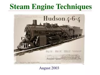
Why Steam Engine? • Steam Engine is preferred over IC Engine, Because • Higher Power Output & Higher Efficiency (Double Acting) • Low Noise • Low Atmospheric pollution (No CO) • Fuel flexibility (Natural gas Coal etc) • Note : It is mostly used in Railways MOAZ HASSAN
Thank You ! Applied Thermodynamics & Heat Engines