Download
1 / 1
30 likes | 137 Views
Hydrostatic Pressure Cell Design for Cryogenic Operation in Pulsed Magnetic Fields. Student: Isaiah Helm Mentor: Chuck Swenson NHMFL – Los Alamos National Laboratory. ABSTRACT:

E N D
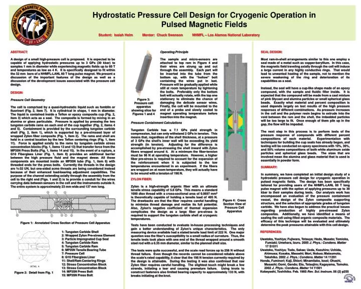
Hydrostatic Pressure Cell Design for Cryogenic Operation in Pulsed Magnetic Fields Student: Isaiah Helm Mentor: Chuck Swenson NHMFL – Los Alamos National Laboratory ABSTRACT: A design of a small high-pressure cell is proposed. It is expected to be capable of applying hydrostatic pressures up to 3 GPa (30 kbar) to samples 1 mm in diameter while experiencing magnetic fields up to 60 T and temperatures as low as 4 K. It is specifically designed to fit within the 32 mm bore of a NHMFL-LANL 60 T long pulse magnet. We present a discussion of the important features of the design as well as a discussion of the development issues associated with the pressure cell design. Operating Principle The sample and micro-sensors are attached to top ram in Figure 4 and their wires are strung up and out through the assembly. Each part will be inserted into the tube from the bottom up, with the “hollow” bolt containing the wires put in last. Pressure will be gradually applied while still at room temperature by tightening the bolts. Preferably only the bottom bolt will actually rotate, with the top one stationary to eliminate the chance of damaging the delicate sensor wires. Finally, the cell will be mounted to the end of a probe and slowly cooled to magnet operating temperature before insertion into the magnet. SEAL DESIGN: Most ram-in-shell arrangements similar to this one employ a seal made of a metal such as copper-beryllium. In this case, the magnetic field traveling axially through the cell will induce a large current in any highly conductive rings. That would lead to unwanted heating of the sample, not to mention the severe weakening of the ring and deterioration of its capabilities as a seal. Instead, the seal will have a cup-like shape made of an epoxy compound, with the sample and fluidic filler inside. It is expected that the compound will be made from a cast mixture of pink Stycast and alumina particles or small spherical glass beads. Exactly what material and percent composition is used depends largely on test results of the high pressure responses of different combinations. As pressure increases in the cell and the polymer resin begins to extrude into the void between the ram and the shell, the imbedded particles will be too large to fit. Once enough of them pile up in the gap, the flow will be impeded. The next step in this process is to perform tests of the pressure response of compounds with different percent compositions of each material. Experimentation with techniques for building the cup seals has already begun, and testing will be conducted on epoxy specimens with 10%, 30%, and 50% volume compositions of both white aluminum oxide particles and spherical glass beads. The sizes that are involved mean the alumina and glass material that is used is essentially in powder form. DESIGN: Pressure Cell Geometry The cell is comprised by a quasi-hydrostatic liquid such as fomblin or fluorinert (Fig. 2, item 7). It is cylindrical in shape, 1 mm in diameter. The liquid is contained inside a Teflon or epoxy composite cup (Fig. 2, item 3) which acts as a seal. The composite is formed by mixing in an alumina or glass particulate. Pressure is applied by pressing the two tungsten carbide rams on each end of the cup together (Fig. 2, items 4 and 5). Containment is provided by the surrounding tungsten carbide shell (Fig. 2, item 1), which is supported by a pre-stressed layer of wrapped Zylon fiber composite (Fig. 1, item 2). The rams and shell are held in a central location by the two Teflon centering rings (Fig. 1, item 11). Force is applied axially to the rams by tungsten carbide stress concentration blocks (Fig. 1, items 12 and 13) that transfer force from the MP35N Press Bolts (Fig. 1, items 14 and 15). In the event of a rupture, a G10 Fiberglass Liner (Fig. 1, item 8) provides an additional barrier between the high pressure fluid and the magnet dewar. All those components are mounted inside an MP35N tube (Fig. 1, item 6) with threaded ends for the press bolts. Currently the threads in the design are ¾-32 UN, but one-sided acme threads are being considered instead because of their enhanced load-bearing adjustment capabilities. The purpose of the channel extending axially through the assembly from the cell to the right end (Figs. 1 and 2) is to provide a conduit for the wires carrying data between sensors in the cell and the instruments outside it. The entire system is approximately 23 mm wide and 137 mm long. Figure 3: Pressure cell apparatus showing slice for Figures 1 and 4 Pressure Containment Calculations Tungsten Carbide has a 7.1 GPa yield strength in compression, but can only withstand 2 GPa in tension. This means that, regardless of the shell thickness, at a pressure of 3 GPa the shell’s inner wall will be exceeding its yield strength (in tension). Adjusting for the difference is accomplished by pre-stressing the shell inward with Zylon fibers wrapped around it. At a minimum the fiber-tension must be 98 N at operating temperature. However, a higher fiber pre-stress is required to account for the expansion of the reinforcement when it is subjected to the low temperatures encountered in an experiment. If the fibers are wrapped on at room temperature, they will actually have to be wound with a tension of 196 N. SUMMARY: In summary, we have completed an initial design study of a hydrostatic pressure cell design for cryogenic operation in pulsed magnetic fields. The design has been specifically tailored for providing users of the NHMFL-LANL 60 T long pulse magnet with the option of applying pressures up to 30 kbar to their samples during tests. Our analysis work has encompassed an evaluation of the pressure containment vessel, the design of the Zylon composite supporting structure, and the selection of appropriate grades of tungsten carbide. We have also begun to address the practical issues regarding production of highly pre-stressed Zylon composites. Additionally, we have identified a means of sealing the cell using filled organic composite materials. The efficacy of this technique will be evaluated and ultimately determine the peak pressures attainable with this cell design. ZYLON FIBER: Zylon is a high-strength organic fiber with an ultimate tensile stress capability of 5.8 GPa. This means a standard 1090 dtex thread with a cross-sectional area of 0.0697 mm2 is theoretically capable of holding a tensile load of 405 N. The drawbacks are that the fiber requires careful handling to minimize thread damage and realize its full potential. Also, Zylon’s negative coefficient of thermal expansion complicates the design as a large fiber pre-stress is required to support the tungsten carbide shell at cryogenic temperatures. Figure 4: Cross Section View of Pressure Cell Apparatus Figure 1: Annotated Cross Section of Pressure Cell Apparatus Tests have been conducted to evaluate in-house processing techniques and gain a better understanding of Zylon’s unique characteristics. The only measuring device available had a stated tensile load limit of 222 N. One major question was the fiber’s susceptibility to a small radius of curvature. Thus, the tensile tests took place with one end of the thread wrapped around a smooth steel rod with a 6.35 mm diameter, similar to the planned shell size. The tests were quite successful, and the scale read forces up to 258 N without thread failure. Even though the records cannot be considered reliable above the scale’s rated capability, it clear that the 196 N tension currently required by the design is attainable. During the testing it was also confirmed that raw Zylon fiber requires careful handling. The slightest touch might break a few strands, initiating a tear and causing premature failure. Using knots to construct fasteners also limited bearing capacity to approximately 133 N, with breaks initiating at the knot. 1: Tungsten Carbide Shell 2: Wrapped Zylon Pre-stress Element 3: Particle Impregnated Cup Seal 4: Tungsten Carbide Ram 5: Tungsten Carbide Ram 6: MP35N Tensile Bearing Tube 7: Pressure Cell 8: G10 Fiberglass Liner 11: Shell/Ram Centering Rings 12: Stress Concentration Block 13: Stress Concentration Block 14: MP35N Press Bolt 15: MP35N Press Bolt REFERENCES: Uwatoko, Yoshiya; Fujiwara, Tetsuya; Hedo, Masato; Tomioka, Fumiaki; Umehara, Izuru. 2005 J. Phys.: Condens. Matter 17 S1011 Uwatoko, Yoshiya; Todo, Sakae; Ueda, Kazuhiro; Uchida, Ahimusa; Kosaka, Masashi; Mori, Nobuo; Matsumoto, Takehiko. 2002 J. Phys.: Condens. Matter 14 11291 Honda, Fuminori; Kaji, Shiori; Minamitake, Issei; Ohashi, Masashi; Oomi, Gendo; Eto, Tetsujiro; Kagayama, Tomoko. 2002 J. Phys.: Condens. Matter 14 11501 Kobayashi, Toshihiko. Feb. 1985 Rev. Sci. Instrum. 56 (2) p255 Figure 2: Detail from Fig. 1