Download

1 / 53
550 likes | 801 Views
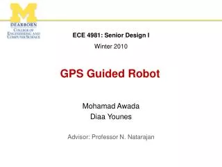
GPS-Guided Autonomous Vehicle. http://cegt201.bradley.edu/projects/proj2001/gpscarjb/. GPS-Guided Autonomous Vehicle. Presentation Overview. Project Summary Project Goals What is GPS? Block Diagram Project Subsystems Hardware Components System Inputs Software Functionality Timeline

E N D
GPS-Guided Autonomous Vehicle Presentation Overview • Project Summary • Project Goals • What is GPS? • Block Diagram • Project Subsystems • Hardware Components • System Inputs • Software Functionality • Timeline • Final Results • Cost Analysis
GPS-Guided Autonomous Vehicle Project Summary The goal of this project is to design and build a vehicle that will be able to navigate from one location on Bradley University's campus to another along the sidewalks without human intervention. In order to do this we have decided to implement a global positioning system (GPS) as the means by which the vehicle will know its position. Heading from a digital compass will be used in conjunction with position information from the GPS receiver to steer the vehicle.
GPS-Guided Autonomous Vehicle Project Goals • Integrate a control system on a self-propelled vehicle utilizing GPS • Implement all controls using a low-cost microprocessor and GPS receiver
GDOP (Geometric Dilution Of Precision) Components: PDOP = Position Dilution of Precision (3-D). HDOP = Horizontal Dilution of Precision (Latitude, Longitude). VDOP = Vertical Dilution of Precision (Height). TDOP = Time Dilution of Precision (Time). .
GPS-Guided Autonomous Vehicle Sample of DGPS data Horizontal Standard Deviation : 104.9 meters
GPS-Guided Autonomous Vehicle Sample of DGPS data Horizontal Standard Deviation : 2.3 meters
GPS-Guided Autonomous Vehicle GPS Module • Problems With Differential GPS • Accuracy was not improved, and sometimes even reduced • Correction signal is transmitted over a range that adds error. ( 1m error for every 100 km (62 miles) ) • Maximum broadcast range = 450 km (280 miles) • Signal latency can be as great as 3 to 5 seconds • Correction signal and receiver signal are determined by different clusters
GPS-Guided Autonomous Vehicle The Solution • Dead-Reckoning • Uses a digital compass to account for the errors of GPS. • Normally used while satellites are not visible. • We are incorporating this concept by using the compass to control the steering.
GPS-Guided Autonomous Vehicle Digital Compass • 2 degree accuracy, 1 degree resolution • 5Hz sampling rate (software down-sampled to 1Hz) • Pin selectable BCD or binary output format • Power supply: single 5 volt • Size: 1.5"l x 1.3"W x 0.4"H • Weight: 0.2 lbs.
GPS-Guided Autonomous Vehicle Main Project Breakdown • Components • Power Circuitry • Steering control / Linear Actuator • Drive Motors • Subsystems • Digital compass • GPS • Software • Autonomous mode • Diagnostic mode
Block Diagram GPS Receiver GPS Signal Digital Compass Linear Actuator LMD18200 EMAC (H-Bridge) LCD Display Potentiometer Feedback Board Battery 2 Drive Motor Battery 1 Power Circuitry Keypad GPS-Guided Autonomous Vehicle
GPS-Guided Autonomous Vehicle Disciplines Involved • Power electronics • Microprocessor controlled feedback systems • DC Motors • GPS and Differential GPS • RF related interferences • Cross compilers using Assembly and C-code
GPS-Guided Autonomous Vehicle Hardware Components Steering and Drive circuitry
GPS-Guided Autonomous Vehicle Drive Circuitry • Optically Isolated • 12 Volt Bias Supply • Drives Two Motors In Series • Delivers 40 Amps Max Current • Pulse Width Modulated Control Signal
GPS-Guided Autonomous Vehicle Drive Circuitry +12v +12v +5v +12v +12v
GPS-Guided Autonomous Vehicle Voltage Spike 13V 25V
GPS-Guided Autonomous Vehicle Steering Circuitry • H-Bridge Integrated Motor Controller • includes • Bi-directional input control • Brake Control • PWM input • Linear Actuator Attached To The Steering Rod • PWM Controlled Rate of Change • Potentiometer Feedback Position Control
GPS-Guided Autonomous Vehicle Steering Circuitry PWM 10nF +5 V 5 11 Dir 3 10 Brake Feedback +12 V 4 6 7 LMD18200T 10nF 2 1
Steering Drive GPS-Guided Autonomous Vehicle
GPS-Guided Autonomous Vehicle GPS Ashtech G8 Compact OEM GPS Module
GPS-Guided Autonomous Vehicle GPS Module • Completed • Serial Communication between EMAC and G8 • Data acquisition using GPS and DGPS • Acquiring position information
GPS-Guided Autonomous Vehicle Summary of GPS Results • Accuracy varying from 5m to 50m • GPS Heading and velocity accurate only at >2.5 mph. • Accurate position requires up to four hours of stationary data acquisition.
5V regulated 5V regulated ground ground P4.4 P4.3 ground P1.7 P1.4 GPS-Guided Autonomous Vehicle Digital Compass Schematic
GPS-Guided Autonomous Vehicle Software Control Using C-code cross-compiler in Keil programming environment for 8051
GPS-Guided Autonomous Vehicle Software System Description • Steering Control • Sends control signal to actuator to steer towards the desired heading. • Limited to 5 mm of actuator movement per 1 second cycle. (About 3 deg.)
GPS-Guided Autonomous Vehicle Software System Description • Drive Control • Begins with an 40% (fast) duty cycle to overcome initial vehicle inertia. • Maintains a constant duty cycle of 30% (slow) at 100Hz over the course of travel to the motors giving a speed of approximately 1 mph.
GPS-Guided Autonomous Vehicle Software Function • Modes of Operation • Diagnostic Mode • 2 Speed Controls • (fast) and (slow) • Manual Steering Controls Through the 80535 • left and right (5 mm actuator increments) • AutonomousMode • Automatic Speed Control • larger duty cycle to overcome inertia, then slower velocity • Automatic Steering Control • based on digital compass error signal • Automatic Break With GPS Coordinates
GPS-Guided Autonomous Vehicle Project Timeline
GPS-Guided Autonomous Vehicle Final Results MPEG of vehicle driving, and stopping
GPS-Guided Autonomous Vehicle Electronics
GPS-Guided Autonomous Vehicle GPS Sensor
GPS-Guided Autonomous Vehicle Antenna
GPS-Guided Autonomous Vehicle Actuator
GPS-Guided Autonomous Vehicle Cost Analysis
GPS-Guided Autonomous Vehicle Special Thanks To: • Dr. Brian Huggins • Advisor, Customer, and technical writing editor • Dr. In Soo Ahn • Advisor/GPS expert • Mr. Chris Mattus • EMAC guru, connection specialist (and photo editor) • Nick Schmidt • The do-it-all man • Prof. Steve Gustchlag • Power genius • Dr. Gary Dempsey • Cross-Compiler Master And finally...