Download
1 / 23
230 likes | 380 Views
Conductor. Electron . Core. Valence orbit has only one Electron and is loosely bound to core. 29P. Isolated copper Atom. Semiconductor. Energy. Electron . r 3. r 1. r 2. r 2. 14P. r 3. r 1. Center of core. Valence orbit has four electrons. Energy levels in a single atom.

E N D
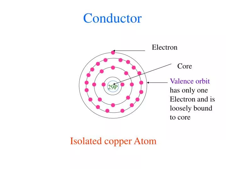
Conductor Electron Core Valence orbit has only one Electron and is loosely bound to core 29P Isolated copper Atom
Semiconductor Energy Electron r3 r1 r2 r2 14P r3 r1 Center of core Valence orbit has four electrons Energy levels in a single atom Isolated silicon atom Electrons in the same orbit has same energy
A silicon crystal is formed by zillions of silicon atoms
Covalent Bond Electron 14P An electron shared by two neighboring atoms to form a covalent bond. This way an atom can have a stable structure with eight valence band electrons. 14P 14P 14P 14P Silicon crystal
Energy bands Electron (in conduction band) Conduction band Hole (in valence band) Valence band Higher band higher energy 14P 2nd band 1st band In a crystal, electrons in the same orbit do not have the same energy and thus form energy bands
Thermal energy produces free electron and hole pair Electron (in conduction band) Hole (in valence band) 14P 14P 14P 14P 14P
Recombination of free electron and hole Electron (in conduction band) Hole (in valence band) 14P 14P 14P 14P 14P
- + - - + + - + - + - + - + + - + - + - Hole/electron flow through a semiconductor Free Electron (in conduction band) 14P 14P 14P A C D F B E 14P 14P 14P Hole (in valence band) The electron moves F-E-D-C-B-A The hole moves A-B-C-D-E-F (pseudo movement)
Intrinsic and extrinsic semiconductor Intrinsic = pure Extrinsic = impure or doped
Doping • Doping meansmixinga pure semiconductor with • impurities to increase its electrical conductivity Can be done in two ways: • Increasing the number of electrons by mixing • pentavalent elements such as phosphorous, • arsenic, antimony (means adding donor impurities) • Increasing the number of holes by mixing • trivalent elements such as aluminum, boron, gallium • (means adding acceptor impurities)
N-type semiconductor Has many free electrons in conduction band and few holes In valence band Free Electron Phosphorous atom 14P 14P 14P 15P 14P
P-type semiconductor Has few free electrons in conduction band and many holes In valence band Hole Aluminum atom 14P 14P 14P 13P 14P
Majority and minority carriers • Electrons are • Majority carriers in N-type semiconductor • Minority carriers in P-type semiconductor • Holes are • Majority carriers in P-type semiconductor • Minoritycarriers in N-type semiconductor
A diode is formed by putting a N-type and P-type of semiconductor together P-N Junction P type N type Anode Cathode Note: Both N and P-type of materials are electrically neutral
+ + - - + + - - - - + + + + - - Migration of holes from P to N And electrons from N to P causes a formation of depletion layer P type N type Anode Cathode This gives rise to barrier potential(Eγ) preventing further migration of holes and electrons
Energy bands in a unbiased diode Depletion layer Energy P N Conduction band Valence band
+ + - - + + - Forward Biased diode P type N type - Anode Cathode R Vγ + - - + VB
Energy bands of a forward biased diode Smaller depletion layer Energy P N Conduction band Valence band
Forward Biased diode • The diode behaves like a ‘ON’ switch in this mode • Resistance R and diode’s body resistance • limits the current through the diode • VBhas to overcome Vγin order for the diode to • conduct
+ + + - - - + + + - - - - - - + + + + + + - - - Reverse biased diode Larger depletion layer P type N type Cathode Anode - + VB
Energy bands in a reverse biased diode Larger Depletion layer Energy P N Conduction band Valence band
Reverse Biased diode • The diode behaves like a ‘OFF’ switch in this mode • If we continue to increase reverse voltage VB • breakdown voltage of the diode is reached • Once breakdown voltage is reached diode conducts • heavily causing its destruction
Breakdown • Diode breakdown is caused by thermally • generated electrons in the depletion region • When the reverse voltage across diode reaches • breakdown voltagethese electrons will get • sufficient energy to collide and dislodge other • electrons • The number of high energy electrons increases • in geometric progression leading to an avalanche • effect causing heavy current and ultimately • destruction of diode