Download
1 / 35
350 likes | 504 Views
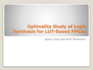
Compile-time Area Estimation for LUT-based FPGAs. Dhananjay Kulkarni Dept. of Computer Science University of California, Riverside. Oct 5 th 2001. Overview. Background The Cameron Project Motivation Compile-time Estimation Approach Experimental Results Conclusion. Config. memory.

E N D
Compile-time Area Estimation for LUT-based FPGAs Dhananjay Kulkarni Dept. of Computer Science University of California, Riverside Oct 5th 2001
Overview • Background • The Cameron Project • Motivation • Compile-time Estimation Approach • Experimental Results • Conclusion
Config. memory FF 3 Reconfigurable Hardware • Field programmable gate arrays (FPGAs) • a grid of logic blocks, with interconnect wires interleaved • functionality of each logic block, interconnect is programmable • reconfiguration time • low clock speeds, but large parallelism
How do we program to map to hardware ? Circuit based approach Hard to learn, code partitioning, time consuming, synchronization, timing, manual translation Algorithmic approach Easy to learn, no issues of low-level design, automated translation Programming FPGAs Application RCS
Time consuming Issues in typical approach Problem Definition • User handles the timing and synchronization • Placement, routing and optimization are time intensive (order of hours or days) • Resource usage and timing are available only at the final stage of the design • Inability to meet constraints implies repeating the entire cycle Behavioral description using VHDL/Verilog High Level Synthesis Placement Routing Optimizations N Constraints met? Y Ready to run on FPGA
Cameron Project Overview • Goal: To bridge the semantic gap between applications and FPGAs • Algorithmic approach • Targets image-processing applications • Integrated environment • SA-C Language, Compiler, Translator, Simulator, … • Easy of programming in SA-C makes FPGAs available to more programmers
Time consuming Overview of SA-C compilation DFG to VHDL Translator vhdl Synplify (Synthesis + mapping) SA-C program prj xnf dfg Xilinx Tools (place and route) SA-C compiler x86 Host code c gcc Host RCS executable
SA-C compilation uint20 [:,:] main (uint8 image[:,:], uint8 kernel[:,:]) { uint20 res[:,:] = for window win[3,3] in image { uint20 val = for elem1 in win dot elem2 in kernel return(sum((uint20)elem1*elem2)); } return(array(val)); } return (res); Optimizations Sassy Source Code SA-C DFG C VHDL Host Code
SA-C • Expression-oriented, functional language • C-like syntax, restricted by: • non-recursive • single assignment • no pointers • True-multi dimensional arrays • Rich set of numeric data types • Powerful loops • Multiple-valued returns
Input Input Input Generator ILB Generic inputs Constant inputs Write DFG node Output Output Output Output SA-C dataflow graphs • Direct mapping from (high level) functional languages to DFGs • DFGs are optimized • Direct mapping from DFG nodes to FPGA logic blocks • Direct mapping from DFG edges to wires
Classification of DFG nodes • Arithmetic: perform common function such as addition and logical operations. E.g. UADD, USUB, ULT • Bit: perform shift, sub-word selection and width change operations. E.g. L-SHIFT, CHANGE-WIDTH • Selector: perform choosing one from the number of inputs. E.g. SELECTOR • Generator: take token sequences and use them to specify output tokens. E.g. ELEMENT-GENERATOR, WINDOW-GENERATOR • Reduction: take token sequences and reduce or store them. E.g. USUM-VALUES, UMAX-VALUES • I/O: handle the interface between the DFG and the outside world. E.g. INPUT, OUTPUT
Compiler optimizations/transformations • Optimizations are applied before generating the DFG • Code motion, constant folding, array and constant value propagation minimize calculations • Loop unrolling, loop fusion, strip-mining increase the parallelism • Resources are limited. A good design uses ~ 70 % FPGA (max) • Compiler need to know the effect of optimizations on the LUT usage
Does not fit! loop unrolling + other optimizations <loop body 1> <loop body 2> <loop body 3> . . Inner Loop Body Resources are limited! for <generator> { <loop body> } <return values>
Humm..can I estimate area? Need to estimate SA-C compiler optimizations try to explore coarse-grained and fine-grained parallelism DFG to VHDL Translation Synthesis tool does area and timing optimization Place and route LUTs are limited Starts with a SA-C program ~msecs ~msecs ~mins ~hours
Motivation • SA-C compiler performs various optimizations • Optimizations affect the area • Resources are limited, thus compiler needs a feedback • Estimation should be done before the synthesis phase • Estimation process has to be quick and relatively accurate • Compile-time estimation at an intermediate form used by compiler • Estimation results serve as feedback to aid in compiler optimizations
Goal • Objective • To provide quick and relatively accurate area estimation of a SA-C source program (on the target FPGA), that serves as feedback to the SA-C compiler to aid in complier optimizations. • Input: SA-C dataflow graph • Output: % LUT usage on target FPGA • Approach • Does not incorporate scheduling, resource allocation, binding • Uses general formulae to estimate the LUT usage of SA-C DFG
% area usage on FPGA Estimation Compile-time estimation SA-C Compiler DFG Optimizations DFG to VHDL Translator VHDL Synthesis + placement + routing Time consuming FPGA configuration code
SA-C dataflow graph The estimator uses the DFG generated by the compiler and the nodeparams file as input and outputs the area usage of the SA-C program Estimation Program Area estimations Steps in building the estimation model Instances of vhdl entities created by varying the generic inputs Log files generated by synthesis tool Regression analysis Generic inputs DFG node log 1 vhdl 1 log 2 vhdl 2 Logic Synthesis General formula that approximates the area usage of DFG node log N vhdl N F(x) = … Nodeparams file F(x1) F(x2) F(x3) Data file that stores the coefficients for the general formulae
The Abstract Machine All modules mapped to a single FPGA (1 PE model) Combinational Window Generators Window Generators Sequential Inner Loop Body Memory Arbitrator Write Data Write Data Compiler generated DFG mapped to VHDL Preset VHDL modules • Reasonable target for the compiler during translation process • DFG2VHDL Translator interfaces the appropriate signals • Estimation works well for combination logic • Area usage of preset VHDL modules is pre-computed
Estimation algorithm Input: DFG dfg(G,V) , FILE nodeparams Step 1. Parse dfg Step 2. For each node n in dfg do Step 3 - 6 Step 3. Identify generic parameters g Step 4. Identify the type of general formula to apply Step 5. Read the general formula f(x) and the coefficients s from nodeparams Step 6. Estimated LUTs = f(g) Step 7. Apply heuristics on dfg Step 8. Record statistical information Step 9. Calculate Total LUT usage on target FPGA Output: % LUT usage Algorithms and formulae are low in complexity
General formulae • The general formulae are classified as: • Constant: y= C • Linear: y = p0 + p1 * x • Quadratic:y = p0 + p1 * (x – p2) 2 • BiProduct:y = (z-p0) * (x-p1) + p2 • MultiLinear2: y = c0 + (c1 * x/2) (z/2 – 1) • y gives the estimated LUT usage as function of bit-width (x) and/or • num-of-vals (z) • C, p0, p1, p2, c0, c1 are the coefficients that are recorded in the • nodeparams file
General formulae - 1 Constant: y = C Nodes that synthesis as signals/wires and provide interface with the outside world, such as INPUT, OUTPUT Linear: y = p0 + p1*x Arithmetic nodes, such as UADD, USUB UADD node with linear approximation
General formulae - 2 Quadratic:y = p0 + p1*(x-p2)2 Expensive arithmetic operations such as UMUL, IMUL UMUL node with quadratic approximation
General formulae - 3 BiProduct:y = (z-p0)*(x-p1) + p2 Multi-input arithmetic nodes that support arbitrary number of input values with associated boolean mask, such as USUM-MANY USUM-MANY node with biproduct approximation
General formulae - 4 MultiLinear:y = c0 + (c1*x/20) (z/2-1) Multi-input logic operators that allow an arbitrary number of input values, each with associated boolean mask, such as AND-MANY AND-MANY node with multiLinear approximation
Estimation Heuristics • Purpose is to use simple techniques to account for the optimized logic • Based only on structural patterns • Example 1: Multiplication by constants Io 2 Io dfg2vhdl/synthesis UMUL Shift register Oo clk Oo • Example 2: Comparison nodes [ 7: 0 ] [ 7: 0 ] [ 7: 0 ] [ 7: 0 ] dfg2vhdl/synthesis UADD + [ 8: 0 ] [ 7: 0 ] < 25510 11111111 b ULT Bit 8 MUX SELECTOR
Experimental setup • All SA-C codes are compiled for Annapolis Micro System Inc.’s WildStar board • Target FPGA: Xilinx Virtex FPGA XCV1000 (27648 LUTs / FPGA) • Experiments • Image-processing operators • Image-processing benchmarks • Effect of compiler optimizations • All results compared with synthesis/mapping reports from Synplify
IP benchmarks LUT estimation Estimation time 5 to 6 orders faster than synthesis tools!
Effect of optimizations uint20 [:,:] main (uint8 image[:,:], uint8 kernel[:,:]) { uint20 res[:,:] = // PRAGMA (stripmine(4,3)) for window win[3,3] in image { uint20 val = for elem1 in win dot elem2 in kernel return(sum((uint20)elem1*elem2)); } return(array(val)); } return (res); • Convolution • Stripmine (4,3), (5,3), (6,3), (7,3) (8,3) and (20,3)
Stripmining results • Loop stripmining when followed by full loop unrolling produces the effect of multidimensional partial loop unrolling. • Compiler can make choice of the window size • Optimization can be applied transparent to the user
Prewitt + Threshold • 2 loops running on the reconfigurable board, one of them being activated multiple times • // Prewitt • int8 V[3,3] = { {-1, -1, -1}, { 0, 0, 0}, { 1, 1, 1} }; • int8 H[3,3] = { {-1, 0, 1}, {-1, 0, 1}, {-1, 0, 1} }; • uint8 R[:,:] = for window W[3,3] in Image { • int8 iph, int8 ipv = • for h in H dot w in W dot v in V • return(sum(h*w), sum(v*w)); • uint8 mag = sqrt(iph*iph + ipv*ipv); • } return( array(mag) ); • // Threshold • uint8 T[:,:] = for pix in R{ • uint8 t = pix>127 ?255 : 0; • } return(array(t));
Prewitt + Threshold • Loops fused • uint8 T[:,:] = for window W[3,3] in Image { • int8 iph = (W[0,2]+W[1,2]+W[2,2]) - (W[0,0]+W[1,0]+W[2,0]); • int8 ipv = (W[2,0]+W[2,1]+W[2,2]) - (W[0,0]+W[0,1]+W[0,2]); • uint8 mag = sqrt(iph*iph + ipv*ipv); • uint8 t = mag>127 ? 255 : 0; • } return( array(t) ); • Only 1 loop running on the reconfigurable board • activated once • Reduces memory traffic
Prewitt + Threshold • Loop stripmined • uint8 T[:,:] = for window W[4,3] in Image step(2,1) { • int8 iph1 = (W[0,2]+W[1,2]+W[2,2]) - (W[0,0]+W[1,0]+W[2,0]); • int8 ipv1 = (W[2,0]+W[2,1]+W[2,2]) - (W[0,0]+W[0,1]+W[0,2]); • uint8 mag1 = sqrt(iph1*iph1 + ipv1*ipv1); • uint8 t1 = mag1>127 ? 255 : 0; • int8 iph2 = (W[1,2]+W[2,2]+W[3,2]) - (W[1,0]+W[2,0]+W[3,0]); • int8 ipv2 = (W[3,0]+W[3,1]+W[3,2]) - (W[1,0]+W[1,1]+W[1,2]); • uint8 mag2 = sqrt(iph2*iph2 + ipv2*ipv2); • uint8 t2 = mag2>127 ? 255 : 0; • uint8 t[2,1] = {{t1},{t2}}; • } return( tile(t) ); • Only 1 loop running on board • activated once • Only half the iterations as before
Conclusion • Compile-time estimation is developed to aid in compiler optimizations • Estimation technique is based on general formulae • Estimation is quick (average estimation time: 1 millisec) • Errors in estimation • Small IP operators: 3.03 % • Large benchmarks: 5.3 % • Worst case error: 10.32 % • Specific to Xilinx XCV1000 FPGA • Can be easily extended to other variety of FPGAs in future