Download
1 / 25
250 likes | 369 Views
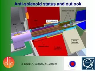
CLIC WORKSHOP SiD SOLENOID STATUS REVIEW. Wes Craddock SLAC October 13, 2009. SiD & MAGNET STATUS. DETECTOR GENERAL STATUS The Silicon Detector is one of three remaining detector concepts for the ILC LOI Submitted March of 2009 Concept Validated August 2009 CDR Due 2012

E N D
CLIC WORKSHOP SiD SOLENOID STATUS REVIEW Wes Craddock SLAC October 13, 2009 SiD STATUS REVIEW Wes Craddock
SiD & MAGNET STATUS DETECTOR GENERAL STATUS The Silicon Detector is one of three remaining detector concepts for the ILC LOI Submitted March of 2009 Concept Validated August 2009 CDR Due 2012 MAGNET GENERAL STATUS Initial Design and Field Calculations by Rich Smith & Bob Wands (FNAL) First Pass General Design (LOI) Completed Design is Based on CMS Design, Construction Techniques and Conductor Preliminary Detailed Engineering Design with Overall Construction Drawings Due at the End of 2010 (SLAC Objective). SiD STATUS REVIEW Wes Craddock
SiD STATUS REVIEW Wes Craddock
SiD MAGNET DESIGN RESOURCESTHROUGH DECEMBER 2010 MANPOWER ~ 1 Full Time Equivalent Wes Craddock < 60 % Magnetic Field Calculations, Structural Calculations, Marco Oriunno ~ 15 % Detector Integration and Assembly with Detector, Tolerancing, Vibration Analysis? Designer ~ 15 % Others; Maybe? 10%: John Weisend? (Cryo integration with QD0) FINANCIAL ~ $50,000 for Conductor R&D SiD STATUS REVIEW Wes Craddock
SiD SOLENOID MAJOR DESIGN TASKS • 3D MAGNET FIELD CALCULATIONS FOR SOLENOID & DID COMBINED FIELDS AND FORCES • 2D/3D MAGNETIC FIELD CALCULATIONS FOR STRAY FIELDS • INTEGRATION OF THE DID COIL WITH THE SOLENOID • ASSEMBLY AND INSTALLATION PROCEDURES • OVERALL TOLERANCES AND FINAL SIZE SPECIFICATIONS • STRUCTURAL ANALYSIS OF COIL PACKAGE, SUPPORTS AND VACUUM SHELL • ENGINEERING DRAWINGS • CRYOGENIC INTEGRATION OF THE SiD SOLENOID WITH QD0 • CONDUCTOR R&D SiD STATUS REVIEW Wes Craddock
SiD SOLENOID OTHER DESIGN TASKS • DESIGN OF THE DID COIL • SUPPORT RODS, CURRENT LEADS, CHIMNEY, VACUUM PUMPING, HELIUM DEWAR, TRANSFER LINES, PRESSURIZED WATER COOLED DUMP RESISTOR • INTEGRATION OF THE DID COIL WITH THE SOLENOID • BETTER COST ESTIMATES • ITEMS NOT TO BE CONSIDERED BY END OF 2010 • POWER SUPPLY, DUMP SWITCH, INSTRUMENTATION • (Except for overall size, number of items etc.) • SCHEDULE, MAINTENANCE, RELIABILITY • DETAILED COST ESTIMATE • NO SAFETY DOCUMENT SiD STATUS REVIEW Wes Craddock
SiD --- CMS Solenoid Comparisons SiD STATUS REVIEW Wes Craddock
Solenoidwith Integrated Dipole Baseline design: 6 layers CMS conductor 1.6 GJ, ~18000 Amperes Dipole Solenoid SiD STATUS REVIEW Wes Craddock
B Field optimization 50 gauss 50 gauss Gap 1cm, flux return plates Gap 5cm, flux return plates 50 gauss Gap 1cm, no flux return plates SiD STATUS REVIEW Wes Craddock
Cryogenics system design for push-pull • Stationary cold box with flexible cryo-transfer line • Minimize risks vs. a moving cold box with high pressure He flexible line • Cold boxes interconnection with redundancy feature for temporary unavailability Interconnection Cold box A Cold box B Flexible cryo-line Detector B Detector A SiD STATUS REVIEW Wes Craddock
Cryogenics layout SiD STATUS REVIEW Wes Craddock
Flexible Cryo-line A Cold box A Solenoid Detector A Interconnection Beam Line Cold box B 30 m Solenoid Detector B Garage SiD STATUS REVIEW Wes Craddock
SiD Superconducting Dipole – Anti Dipole 4.5 K Detector Integrated Dipole “anti” Dipole with magnetic field profile. Dipole field is horizontal. Gaps in dipole winding are connection points to current leads SiD STATUS REVIEW Wes Craddock
Superconducting DID Design and Construction • The 4 DID coils shown above is most likely the easiest configuration to assembly and integrate with the solenoid. • Other designs separate the 4 main coils into sub coils. This would create substantial difficulties in radial tie rod placement. • PROPERTIES: 1) 600 G with 8 MJ added to total stored energy 2) 550 kA-turns @ 700 A; 4 layers/197 turn layer 3) 3 mm X 4 mm aluminum coextruded SC at 1/3 Ic 4) Flat wound coils between Al sheets; bent to correct radius; vacuum impregnated, bolted to OD of solenoid mandrel, attached with thermal straps. SiD STATUS REVIEW Wes Craddock
SiD SUPERCONDUCTING SOLENOID CONDUCTOR • The superconducting solenoid is the single most costly (M&S) and risky item in the SiD Detector • SiD Baseline Design uses the CMS Conductor (shown below) • Is there a cheaper easier better conductor? • The ATLAS Superconducting Central Solenoid points the way with Al- 0.1wt% Ni alloy SiD STATUS REVIEW Wes Craddock
MOTIVATION FOR CONDUCTOR DEVELOPMENT • Is there an easier/cheaper way to produce an equivalent CMS conductor with only 1 aluminum alloy that has equivalent strength to the composite CMS. • A coupled transient current diffusion/thermal diffusion ANSYS model was produced to ensure equivalent CMS superconductor stability • This ANSYS analysis demonstrates that equivalent CMS conductor stability can be achieved by replacing the high purity and structural aluminum with a single type of aluminum having 1/3 the electrical and 1/3 the thermal conductivity of the high purity aluminum. Thus the use of much higher strength aluminum can be used. • Analysis is more difficult when high purity aluminum is used because of complex changes in the plastic state. • The SiD solenoid has higher radial stress than CMS • Total conductor volume probably cannot be reduced by much since we are at the CMS state of the art 12 kJ/kg quench thermal stress limit. SiD STATUS REVIEW Wes Craddock
ANSYS CONDUCTOR STABILITY ANALYSIS A B CMS Conductor 0.5 J at Center A & B Current Diffusion / SC Cable Removed A at 3 msec; B at 54 msec C Thermal Profile at 54 msec Notice: 1) Current only diffuses a relatively small distance into the aluminum. 2) Temperature wave does not reach 60 cm point. 3) Heat is trapped in the structural aluminum at 54 msec C SiD STATUS REVIEW Wes Craddock
SiD CONDUCTOR OPTIONS Option 1 Option 2 Dilute high purity Al alloy or high purity Al matrix with superconducting cable and two high strength wire ropes Dilute high purity Al alloy or high purity Al matrix with superconducting Rutherford cable CMS conductor must carry 130 kN = 94 MPa (avg) of hoop load With the assumption that all the CMS hoop load is carried by its structural aluminum with a safety factor of 2.4 on 4 K yield, the average required 4 K aluminum alloy yield stress for SiD is 225 MPa unless option 2 is used. Note: High purity aluminum has a 4 K yield of 10 MPa = 1500 psi SiD STATUS REVIEW Wes Craddock
DILUTE ALUMINUM ALLOY STABILIZER OPTIONS • In general, impurities in solid state solution with aluminum are bad. • Precipitates are less damaging than solutes to aluminum electrical conductivity. • Most aluminum alloys considered for stabilizers work by precipitating out the dissolved microalloying element as an intermetallic (e.g. Al3Ni) • Cold working is essential to increasing strength but is also detrimental to electrical conductivity • Dilute high purity Al-Ni are the best characterized 4 K enhanced aluminum stabilizers. • High purity Al with 0.1 wt.% Ni was used for the ATLAS Central Solenoid. With 21% cold working and final aging during the epoxy cure cycle, the alloy had an RRR = 590 and a 4 K yield of 110 MPa. Alloys with up to 2% Ni have been characterized. • Perhaps two dozen other Al binary systems have been studied but virtually none have both 4 K strength and electrical conductivity measured. • Al microalloys of cerium and yttrium hold substantial promise. SiD STATUS REVIEW Wes Craddock
ALUMINUM NANOCOMPOSITES • There is even less information on the 4 K properties of aluminum nanocomposites than on dilute aluminum alloys. Yet, they look very promising. • For example, the strength of Al-1%Si3N4 (15 nm) equals that of Al-15%SiC (3.5 μm) • Candidate reinforcing nanoparticles include SiC, Al2O3, TiC, BN, AlB2, AlN, B4C, AlB2O3, and TiB2. • TiB2 is of particular interest because it is used in industrial quantities as a grain refiner in aluminum alloy production, and there is a lot known about it. • Nanocomposites can be produced In situ (via chemical reaction in molten aluminum) or ex situ by addition of nanocomposites to molten aluminum or by powder metallurgy. • Small test samples can be produced by many different small R&D type companies. SiD quantities of 80,000 kg must probably be produced by molten aluminum technology using electromagnetic stirring and/or ultrasonic cavitation. SiD STATUS REVIEW Wes Craddock
ALUMINUM / CARBON NANOTUBES • Aluminum reinforced with carbon nanotubes is the most intriguing of the nanocomposites. It comes in single walled and multiwalled. Multiwalled is the cheapest(~ $500 to $5000/kg) and is the only one considered here. • At the present time there are only about 20 published papers discussing aluminum carbon nanotube composites. • Carbon nanotubes are incredibly strong and stiff. • Much debate and theoretical work is being done on carbon nanotube electrical properties. Some reports show them to be ballistic conductors. Some reports show that they can have a critical current carrying capacity of 109 A/cm2. Electrical resistivity of Al carbon nanotube composite 99.5 % Al + 10 wt % nanotube 30 nm X 200 nm to micrometers long 1% and 4% nanotube graphs are very similar From C.L. Xu et. al. Carbon 37 (1999) SiD STATUS REVIEW Wes Craddock
ALUMINUM / CNT MANUFACTURING • Although CNTs may hold the greatest promise for high purity aluminum reinforcement, they are the most difficult material to produce at least on an industrial scale. • Molten aluminum does not wet CNTs • CNTs come tangled • CNTs stick together by Van der Waals forces and agglomerate at grain boundaries. • To date all Al-CNT composites have been produced by powder metallurgy. This is mostly likely very difficult on an industrial scale. • Try the liquid metal route using one or more of the following techniques: • Plate the CNTs; electroless Ni or Cu; vapor deposit Ti, Nb, NbTi, Ce? Y?. • Disperse the CNTs with electromagnetic stirring and/or ultrasonic cavitation. • Rheocasting (semi-solid casting) SiD STATUS REVIEW Wes Craddock
AL-Sc Alloys, ECAE, and Conklad Extrusion • Scandium is unique among all possible elements that could be used to create dilute high purity aluminum alloys. • Simply stated Sc is a powerful grain refiner, provides the greatest increment of strength per atom, and is the most powerful antirecrystallization element that can be added to aluminum. Al-0.26wt% can raise the recrystallization temperature of aluminum to 600 C. Unfortunately, Sc costs $5500/kg (purchased as 2% master alloy). For SiD this means $1.14 M additional cost. However, lesser amounts would probably be needed since extrusion temperature is only 430 C and rare earth metals can partially substitute for Sc. • Now once we have the AlSc alloy, process it by severe plastic deformation (e.g. equal channel angular extrusion, ECAE) to create a nano grain size aluminum alloy. ECAE involves extruding around a 90 degree angle without changing cross sectional shape. • This material might be best coextruded with the Rutherford cable by the Conklad method (as in ATLAS). SiD STATUS REVIEW Wes Craddock
STAINLESS STEEL ROPE AND EXTRUSION • If an aluminum composite with satisfactory conductivity and strength cannot be found, additional high strength reinforcing must be added. This can be e-beam welded structural aluminum or internal stainless steel rope. • Internal stainless steel rope is the preferred approach for SiD. However, it must have sufficient mechanical bonding with the aluminum and be something that can be coextruded along with the superconducting Rutherford cable. • A company has been located that can produce a small size extrusion with one stainless rope under pretension. Other companies that use the Conform/Conklad process (used for ATLAS) will also be investigated. SiD STATUS REVIEW Wes Craddock
CONCLUSIONS • There are no show stoppers to the SiD solenoid. • CMS and ATLAS design philosophy and engineering experience are the basis of the SiD solenoid design. • Much work remains to produce a first pass set of engineering drawings with not much manpower. • Advanced conductor development is an exciting area of many avenues of approach, potentially benefiting all large detector magnets as well as other areas such as high field MRI magnets. • SLAC would enjoy a collaboration with CERN, INFN and other institutions. • In the USA, LLNL, ANL, Univ. of Texas A&M, and small companies such as Milward and KB alloys (master alloy producers) have expressed substantial interest in collaboration. SiD STATUS REVIEW Wes Craddock