Download
1 / 54
570 likes | 824 Views
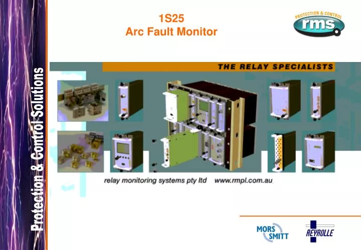
1S25 Arc Fault Monitor. 1S25 Arc Fault Monitor. 1S25 Arc Fault Monitor. Electrical arc short circuits in metal clad switchgear may occur for many different reasons. defective or ageing insulating materials poor bus or cable connections poor maintenance human error

E N D
1S25 Arc Fault Monitor
1S25 Arc Fault Monitor
1S25 Arc Fault Monitor • Electrical arc short circuits in metal clad switchgear may occur for many different reasons. • defective or ageing insulating materials • poor bus or cable connections • poor maintenance • human error • ingress of moisture, dust or vermin • abnormal service conditions
Arc Fault Effects and Consequences ENERGY RELEASED BY ARC FAULT VISUAL & ACCOUSTIC PHENOMENA EFFECTS OF FAULT ARC TEMPERATURE RISE PRESSURE RISE THERMAL STRESSING, MELTING, FIRE VAPOURISATION MECHANICAL STRESSING OF ENCLOSURES CONSEQUENCES FOR PLANT U/V BURNS & EJECTION OF FLAMES & HOT GASES & SMOKE SHOCK WAVE, FLYING DEBRIS, OPENING PANELS CONSEQUENCES FOR PERSONNEL
Switchgear Failure Effects and Consequences
2 secs OC-relay FAULT TIME 110/22 kV PROTECTION TRANSFORMER Switchgear Internal Fault Example 30 MVA
0.07 secs FAULT TIME Arc protection PROTECTION 110/22 kV TRANSFORMER 30 MVA Switchgear Internal Fault Example
Variable Speed Drive Fault Example Water Corporation Western Australia At approximately 0800 hrs on 25/2/07 No.2 VSD failed at Tamworth Pumping Station WA. The PSN electrician was called out to the fault later that same morning and found the main switch compartment of the drive badly damaged. The extent of damage is quite severe and was contained to the main switch compartment of the variable speed drive. The majority of damage appears to have been originated from the VSD main switch, then spreading upon explosion to the upper and rear of the drive and also externally through the ventilation ducts. Earth leakage PROTECTION 22 kV / 690V TRANSFORMER
Variable Speed Drive Fault Example The earth leakage protection on the #2 VSD 22kV / 690V feeder tripped. The O/C protection also detected a phase fault condition. #2 22kV / 690V Transformer circuit breaker was found to be in the OFF position. Judging by the extent of the damage the protection clearly did not respond quickly enough.
Variable Speed Drive Fault Example
Variable Speed Drive Fault Example OPERATOR HAZARD IN ADJACENT CORRIDOR
Variable Speed Drive Fault Example 1S20 ARC FAULT PROTECTION INSTALLED AFTER EARLIER FAULT
Variable Speed Drive Fault Example SUBSEQUENT FAULT As a result of this incident, RMS 1S20 Arc Fault Monitors and 1S30 Arc Flash Sensors were installed. Subsequently several months later another incident occurred, this time due to the failure of the IGBT board. As a consequence, the arc sensors were triggered by tripping the 22kV circuit breaker and as can be seen by the photos the damage was insignificant. 1S30 ARC SENSOR ARC FAULT
Variable Speed Drive Fault Example SUBSEQUENT FAULT ARC FAULT
1S25 Arc Fault Monitor • For moderate arc fault currents the trip time of the over-current stage will be too slow: • For very low arc fault currents the instantaneous trip stage of a standard over-current relay cannot be set low enough.
1S25 Arc Fault Monitor The degree of damage caused by arcing depends principally on the duration of the arc. • ~100ms Arc Fault Duration The switchgear needs to be checked & the insulation resistance measured before power can be re-established. • ~200ms Arc Fault Duration The power supply will be interrupted; the switchgear must be checked; power is re-established only after minor repairs.
1S25 Arc Fault Monitor ~100ms Arc Fault Duration
1S25 Arc Fault Monitor The degree of damage caused by arcing depends principally on the duration of the arc. • ~500ms Arc Fault Duration The supply is interrupted, metal parts of the switchgear are destroyed & poisonous gases are emitted. • ~1s Arc Fault Duration Destroys most of the switchgear & may cause a fire, injury to personnel & damage to property.
1S25 Arc Fault Monitor ~500ms Arc Fault Duration
1S25 Arc Fault Monitor Arguably the greatest risk of arc fault damage exists at the CB cable termination & in the CB chamber itself due to the slow clearance times of the IDMT feeder protection. The problem of arc faults is most prevalent in older metal clad switchgear, which already has operational protection systems. The CB cable termination is particularly at risk to ingress of moisture & rodent damage.
Low Voltage Protection Trip on arc fault <10ms
System Integration With current check using high speed starter element
Single Line Diagram Cable box only Trip only if over current starter picked up
Single Line Diagram Cable box and CT chamber
Single Line Diagram Protect multiple breakers with a single 1S25
Single Line Diagram Cable box, CT and CB chamber
Single Line Diagram Cable box, CB and BUS chamber
Single Line Diagram BUS chamber
1S30 Arc Sensor • Mounted in each segregated switchgear chamber • Sensitivity linear in forward direction through 180º • Detects reflected arc light - mounting position not critical • Optional rear facing sensor • Burden 2.5mA (quiescent)
1S30 Arc Sensor Installation • Mounting position of the Sensor is not critical. • High sensitivity in direction of ‘View’
1S25 System Testing Use camera flash to check operation of arc sensor and pick up of 1S25 trip contact. Typical operating range of flash to arc sensor is 50 to 300mm
1S25 System Testing CRO trace showing nominal operation time of the trip contacts. First contact touch at 6.25ms and fully closed by 7.25ms.
1S30 Arc Sensor Installation 1S30 shown mounted on the outside of a switchgear panel Detector oriented to ‘look’ through a hole into the switchgear
1S30 Arc Sensor Installation 1S30 shown mounted on the inside of a switchgear panel Detector oriented to ‘look’ out into the switchgear compartment
1S30 Arc Sensor Installation The dual optical detector version can be panel mounted to monitor two adjacent switchgear compartments simultaneously.
1S30 Arc Sensor Installation Right angle mounting off a surface Mount off floor or walls within switchgear / BUS bar chamber
1S30 Arc Sensor Installation Flush mount reinforcing plate 1.2mm zinc plated mild steel
SENSOR LOCATIONS 1S30 Arc Sensor Installation
Cable Box Arc Fault 13.1kA (50mS) Fault created in Cable Box by connecting three bushing connectors with fuse wire. Sensor fitted to side of box. Cover after test Cover as new
Cable Box Arc Fault Lower portion of Cover strengthened
Cable Box Arc Fault Sensor location
CB Chamber Arc Fault CB chamber fault at 13.1kA (50mS) Fault initiated by connecting 3 phases of circuit side of CB with fuse wire - typical of test leads used during maintenance. One ARC sensor fitted.
CB Chamber Arc Fault General views after test
1S25 Does it Work • WILL IT OPERATE UNDER DYNAMIC CONDITIONS? --- YES • HOW FAST DOES IT REMOVE AN INTERNAL FAULT? --- 50-75ms • IS IT EFFECTIVE IN ALL SWITCHGEAR CHAMBERS? --- YES • HOW MUCH DAMAGE IS CAUSED TO THE SWITCHGEAR? --- Minimal • DOES IT IMPROVE SAFETY? --- YES, Significantly
measured current ( increase 1*In ==> 10*In) overcurrent detection arc detection trip output contact 1S30 Arc Sensor
1S25 Summary • Up to 8 arc sensors in 4 independent zones • 5 high speed tripping duty arc sense output contacts • <10ms arc fault tripping time • Self supervision with fail alarm contact • Push button reset & self test • 1S30 Arc sensor continuous supervision • Compact, economic design • Simple panel mounting for retrofit applications
1S25 Configuration Settings Bank A & B configuration switches are used to set the number of 1S30 arc sensors connected.