Download

1 / 35
350 likes | 473 Views
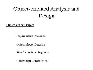
Object Oriented Analysis and Design. Object-Oriented Analysis Statement of what our client wants Object-Oriented Design How to provide it using OO tools. Tasks. Provide a problem statement (requirements analysis) Multiple discussions with client

E N D
Object-Oriented Analysis • Statement of what our client wants Object-Oriented Design • How to provide it using OO tools
Tasks • Provide a problem statement (requirements analysis) • Multiple discussions with client • Determine objects needed to implement the system • Look for nouns in problem statement • Determine object attributes • What do I know? • How are the nouns described? • Determine object behaviors • What can I do? • Look for verbs in problem statement
Key Rule Information Hiding • Though objects know how to communicate with one another across well-defined interfaces, objects are normally not allowed to know how other objects are implemented
Unified Modeling Language • OOD Tool • We use C++ to communicate our instructions to a computer • Designers use UML to communicate their instructions to those who will do the coding • Important names • Grady Booch • James Rumbaugh • Ivar Jacobsen • All worked at Rational Software in the late 90’s
Problem Statement A company wants to build a two-floor office building and equip it with an elevator. The company wants you to develop an object-oriented software simulator in C++ . Net that models the operation of the elevator to determine whether the elevator suits the company’s needs. Your simulator should include a clock that begins with its time, in seconds, set to zero The clock ticks every second, but it does not keep track of hours and minutes. Your simulator also should include a scheduler that begins the day by scheduling two times randomly: the time when a person first steps onto floor 1 and presses the button on that floor to summon the elevator, and the time when a person first steps onto floor 2 and presses the button on that floor to summon the elevator. Each of these times is a random integer in the range from 5 to 20 seconds, inclusive. When the clock time equals the earlier of these two times, the scheduler creates a person, who then walks onto the appropriate floor and presses the floor button. The floor button illuminates, indicating that it has been pressed. [Note: The illumination of the floor button occurs automatically when the button is pressed and needs no programming; the light built into the button turns off automatically when the button is reset.] At the beginning of the simulation, the elevator starts the day waiting with its door closed on floor 1. To conserve energy, the elevator moves only when necessary. The elevator alternates directions between moving up and moving down.
For simplicity, the elevator and each of the floors have a capacity of one person. The scheduler first verifies that a floor is unoccupied before creating a person to walk onto that floor. If the floor is occupied, the scheduler delays creating the person by one second (thus allowing the elevator an opportunity to pick up the person and move to the floor). After a person walks onto a floor, the scheduler creates the next random time (between 5 and 20 seconds into the future) for a person to walk onto that floor and press the floor button. When the elevator arrives at a floor, it resets the elevator button and sounds the elevator bell (which is inside the elevator). The elevator then signals its arrival to the floor. The floor, in response, resets the floor button and turns on the floor's elevator-arrival light. The elevator then opens its door. [Note: The door on the floor opens automatically with the elevator door and needs no programming.] The elevator's passenger, if there is one, exits the elevator, and a person, if there is one waiting on that floor, enters the elevator. Although each floor has a capacity of one person, assume there is enough room on each floor for a person to wait on that floor while the elevator's passenger exits.
A person entering the elevator presses the elevator button, which illuminates (automatically, without programming) when pressed and turns off when the elevator arrives on the floor and resets the elevator button. [Note: Because the building has only two floors, only one elevator button is necessary; this button notifies the elevator to move to the other floor.] Next, the elevator closes its door and begins moving to the other floor. When the elevator arrives at a floor, if a person does not enter the elevator and the floor button on the other floor has not been pressed, the elevator closes its door and remains on that floor until another person presses a button on a floor. For simplicity, assume that all the activities that happen, from when the elevator reaches a floor until the elevator closes its door, take zero time. [Note: Although these activities take zero time, they still occur sequentially; e.g., the elevator door must open before the passenger exits the elevator.] The elevator takes five seconds to move from one floor to the other. Once per second, the simulator provides the time to the scheduler and to the elevator. The scheduler and elevator use the time to determine what actions each must take at that particular time. The simulator should display messages on the screen that describe what is happening.
Issues in Building a Simulator • World Portion • Items to model • Person • Elevator • Buttons and Lights • Controller Portion • Elements needed to simulate world portion • Scheduler • People Creator
Use Case Diagrams • Helps the analyst complete the requirements analysis • Models the interactions between the system’s external clients and the “use cases” of the system. • Each use case represents a different capability that the system provides to its clients
The goal of the use-case diagram is to show the kinds of interaction users have with the system without providing all of the details. Change Floors
Identifying Classes • Look for the nouns in the problem statement • Company • Building • Elevator • Simulator • Clock • Time • Scheduler • Person • Floor 1 • Floor button • Floor 2 • Elevator door • Energy • Capacity • Elevator button • Elevator bell • Floor’s elevator arrival light • Person waiting on a floor • Elevator’s passenger
Diagram to Associate Classes • Diamond indicates composition • “One object of class Elevator services two objects of class Floor”
Identifying Class Attributes • What Do I know • A class’s attributes are implemented in a C++ program as data • Locate descriptive words and phrases
Class Elevator Clock Scheduler Person Floor Floor Button Elevator Button Door Bell Light Building Descriptive Word/Phrase Waits on floor 1 Alternates direction Capacity of 1 5 seconds to move between floors Elevator moving Begins at 0 Creates the next random time for a person to walk onto a floor Person number Capacity of 1 Occupied/unoccupied Pressed/reset Pressed/reset Shut/open None in problem statement off/on None in problem statement Attributes
State Chart Diagrams • Objects in a system have states • The values of the attributes define the state • State chart diagrams let us express how objects change state
Button has two States Elevator has three states Events that trigger state change are noted next to the dotted lines Text in brackets called “guard conditions”. Stipulates the conditions under which the state change occurs / is an action label. It says that the door is closed after the state is exited Split of servicing Floor state into two compartments means that an action can be performed while in a state (in this case, closing a door)
Activity Diagrams • Focuses on the action that an object performs – as opposed to the state change
Diamonds indicate decisions Text indicates branches of decisions
Class Elevator Clock Scheduler Person Floor Floor Button Elevator Button Door Light Building Verb Phrase Moves, arrives at a floor, resets the elevator button, sounds the elevator bell, signals its arrival, opens its door, closes its door Ticks every second Randomly Schedules times, creates a person, verifies that the floor is unoccupied, delays creating a person by one second Steps onto a floor, presses floor button, presses elevator button, enters elevator, exits elevator Resets floor button, turns off light, turns on light Summons elevator Signals elevator to move Opens, signals person to exit, signals person to enter None in problem statement None in problem statement What Can I do?Look for Verb Phrases
Sequence Diagrams • Models steps that the controlling class repeats • Focuses on how messages are sent among objects over time
Each object is a rectangle The dashed line is the “lifeline” of the object The arrows are messages between objects The message invokes the corresponding operation in the receiving object. The dashed line represents the value returned by the object The text to the far left is the constraint the sequence operates under In sum: Building sends a tick message to Clock Building sends a getTime message to clock Clock returns time to Building Building sends a processTime message to Scheduler, passing the current time (the Scheduler must decide whether to create a person) At this point, and before the Building sends a processTiome message to the elevator, lots of things happen a shown on the next slide
The bar on the edge of the Scheduler bar is what happens when an object sends a message to itself (delayTime(floor1)) If occupied is false, the scheduler creates an instance of class Person
Interactions Among Objects • When two objects interact • A message sent by one object • Invokes an operation in another object
Interactions I Sender Message Receiver Elevator resetButton ElevatorButton ringBell Bell elevatorArrived Floor openDoor Door closeDoor Door Clock Scheduler stepOntoFloor Person isOccupied Floor Person pressButton FloorButton pressButton ElevatorButton passengerEnters Elevator passengerExits Elevator passengerArrives Floor Floor resetButton FloorButton turnOff Light turnOn Light
Interactions II Sender Message Receiver FloorButton summonElevator Elevator ElevatorButton prepareToLeave Elevator Door exitElevator Person enterElevator Person Bell Light Building tick Clock getTime Clock processTime Scheduler processTime Elevator
Collaboration Diagram A collaboration consists of a collection of objects that work together to perform a task. • Interacting objects are connected with solid lines • Objects pass messages along these lines in a direction indicated by arrows. • A sequence of messages proceeds in numerical order.
Elevator sends resetButton message to Elevator Button • Elevator rings bell • Elevator sends arrival message to floor • Floor sends reset button message • Floor sends turn on light message • Elevator sends openDoor message to Door • Door sends exitElevator message to passenger • Person sends passengerExit message to Elevator • Door sends enterElevator message to waiting person • Passenger sends passengerEnters message to Elevator
Header Files (First Pass) BuildingElevator Button BellElevator LightScheduler DoorPerson Clock Floor Floor Button
Inheritance We have a Class Crypto and two sub-classes derived from Crypto: Monoalphabetic and Polyalphabetic. We represent the structure in UML like this: Crypto Monoalphabetic Polyalphabetic