Download
1 / 13
130 likes | 511 Views
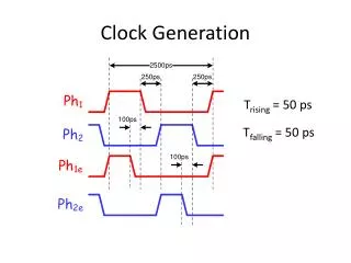
CLOCK. Sephiroth Kwon GRMA 20-05-2009. OUTLINE. Clock Distribution Diagram Signal Description Repair Flow Chart Repair Technique. CLOCK Distribution Diagram. MCHHCLK/# 200/266MHZ. P5Q Deluxe. Clock Chip. Intel BearLake GMCH. DDR2 1,2,3,4. M_CHB_CLK/#. CK_100M_MCH/# 100MHZ.

E N D
CLOCK Sephiroth Kwon GRMA 20-05-2009
OUTLINE • Clock Distribution Diagram • Signal Description • Repair Flow Chart • Repair Technique
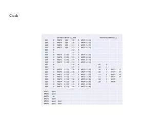
CLOCK Distribution Diagram MCHHCLK/# 200/266MHZ P5Q Deluxe Clock Chip Intel BearLake GMCH DDR2 1,2,3,4 M_CHB_CLK/# CK_100M_MCH/# 100MHZ CPUHCLK 200/266/333MHZ CK_96M_DREF/# 96MHZ Intel ICH9 CK_100M_ICH/# 100MHZ Intel LGA775 CK_100M_SATA/# 100MHZ BITCLK 24MHZ CK_33M_ICH/# 33MHZ AUDIO Code CK_48M_USB/# 48MHZ CK_14M_ICH/# 14.318MHZ CK_33MHZ PCI Slot CK_100M_PE16/# 100MHZ PCIEx16 Slot VIA6308 CK_100M_PE1/# 100MHZ PCIEx1 Slot TPM CK_100M_PE1/# 100MHZ Attansic L1 CK_48M_SIO 48MHZ W83667EHF CK_33M_SIO 33MHZ
CLOCK Distribution Diagram M4N78 AM
CLOCK Distribution Diagram M4A79 DELUX
Signal Description South Bridge 1.Sometimes the Clock chip connect one Diode or BJT component. It depends on designer. 3V 3V 3V 3V Inductor Inductor Clock Generator Clock Generator 14.318 MHZ 14.318 MHZ PG PG Diode BJT Figure A. Figure B. SLP_S3# SLP_S3#
Signal Description • Sometimes we can find BAT54AW near ICS. • VRMPWRGD and SLP_S3# must be 3V • Finally, CLKVCC offer 3V PWRGD to Clock Generator. • If Clock Generatordoesn’t work, you must measure this PWRGD signal first.
Repair Flow Chart START Visual Inspection check CLK Gen. and related small components are ok NG Change damaged CLK Gen.& NG components OK OK NG Measure CLK Gen. Voltage Input Check CLK Vcc 3V & related trace component Fix any trace open and change any NG RLC component OK NG OK NG Measure X’TAL 14.318Mhz is ok OK NG Check X’TAL & related two Capacitors are ok Change NG X’TAL or Capacitor NG OK Check which CLK signal is wrong Trace the circuit, check related trace & resistor, capacitor Fix any trace open and change any NG RLC component OK NG NG OK Change CLK Generator Finished
Repair Technique-Visual Inspection Visual Inspection to check Clock Generator and related small components are not damaged. 1
Repair Technique-Measure Vcc_CLK Use Multi-Meter or Oscilloscope to measure Clock voltage 3.3V is ok. 2
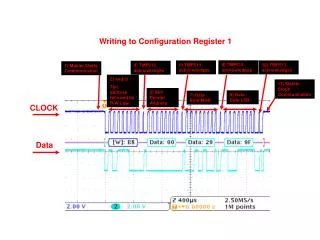
Repair Technique-Measure CLK X’TAL Use Oscilloscope to measure Clock X’TAL 14.318Mhz is ok. 3-1 3-2
Repair Technique-Check Individual NG signal Use Oscilloscope to measure every individual CLK signal. If find error please trace the circuit to find it’s connection. If related RLC components are ok but CLK still is NG please try to change CLK generator at last. 4