Download
1 / 16
220 likes | 516 Views
Effect of Retained Austenite and Residual Stress on Rolling Contact Fatigue. Yi Shen Research Assistant. Outline. Background Motivation Objective Analytical Work Introduction to 2-D FEM rolling contact fatigue model Voronoi tessellations

E N D
Effect of Retained Austenite and Residual Stress on Rolling Contact Fatigue Yi Shen Research Assistant
Outline • Background • Motivation • Objective • Analytical Work • Introduction to 2-D FEM rolling contact fatigue model • Voronoitessellations • 2-D crack initiation and total life of fatigue incorporating residual stress • Experimental Work • Three-ball-on-rod rolling contact fatigue test • Torsion fatigue test • Summary and Future Work
Background of Rolling Contact Fatigue (RCF) • Fatigue: Failure of a component subject to repeated loads that are often well below the ultimate strength or even yield strength of the material RCF in ball bearing (Rosado et al., 2009) Over-rolling components RCF in tribo-components occurs by surface and subsurface initiated spalling Surface originated pitting Subsurface originated spalling • micro-cracks originate below the surface • propagation is towards the surface to form a surface spall • leads to the formation of deep cavities • cracks initiate at a surface irregularity such as a scratch or dent • propagation is at a shallow angle until some critical length or depth and branching towards the surface, removing a piece of material • leads to the formation of shallow craters Subsurface originated spalling is dominant when the bearing is operating under lubricated conditions and free of any surface irregularities such as scratch or dents or any defects
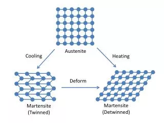
Motivation • Retained austenite (RA) does not transform to martensite upon quenching. The amount of retained austenite has a significant influence on the rolling contact fatigue (RCF) life of steel (SAE 8620) • In addition to any direct effect on life, retained austenite influences the residual stress (RS) profile, which also affects the RCF life of steel • There is no general agreement about the effect of the retained austenite on component durability • Should it be at high (>35%) or low (<5%) levels? • Is there any optimum choice? Retained Austenite (light-colored areas) present in a case carburized component (Daniel, 2005)
Objectives • Determine the optimum amount or range of retained austenite in SAE 8620 steel for rolling contact fatigue (RCF) • Investigate how residual stresses profile influence RCF life • Explore the relationship between retained austenite and residual stresses
Microstructure of steel Modeling of Rolling Contact 6b b=100μm 7b • All physical materials are discontinuous at some level and failure in bearing contacts originates at a micron scale (comparable to the scale of discontinuities) • Rolling contact is modeled by moving a Hertzian Pressure (2GPa - width 2b) across the surface in 21 analytical steps • Induce residual stress (RS) field into the RCF model 10b
2-D Voronoi Element • A set of points (seeds, sites, or generators) is specified and for each seed there will be a corresponding region consisting of all points closer to that seed than to any other • The region is thus referred to as a Voronoi cell[1] 2b 1b Voronoi is a good representation of material microstructure • 33 domains with different Voronoi mesh are generated to statistically investigate the effects of residual stresses on RCF [1] B. Jalalahmadi, F. Sadeghi, 2009, A Voronoi Finite Element Study of Fatigue Life Scatter in Rolling Contacts, ASME J. Trib., 131(2) (2009).
Damage Mechanics [3] Elastic Damage Law [2] • N is number of cycles • Δτ is shear stress reversal along the grain (Voronoi) boundary • τR and m are material dependent parameters • τR= 6113MPa • m = 10.0 Where0<D<1 • Apply damage law to RCF model [2] Robotnov, Y.N., 1969, Creep Problems in Structural Mechanics, North-Holland [3] Xiao, Y.C., Li, S., Gao, Z., 1998, “A Continuum Damage Mechanics Model for High Cycle Fatigue,” Int J Fatigue, 20(7)
2-D Weibull Life Plot without RS • Slope of Jalalahmadi’s result: • Initiation: 5.11 • Total: 4.08 • Slope of current Weibull plot: • Initiation: 7.8 • Total: 4.4 (within 0.51 – 5.7 by Harris and Barnsby, 2001) • Slope of Anurag’s result: • Initiation: 4.81 • Total: 5.13 • Portion of propagation: 64% (within 60%-80%)
2-D Initiation and Total Life Plot constant residual stress Weibull plot for cases with different residual stresses linear residual stress • Residual stresses have very limited influence on crack initiation life • Different kinds of residual stresses have different level of influence on total life • Generally, compressive residual stress will increase the total life of RCF V-shape residual stress
Effect of residual stress on life Increase of life The 2-parameter Weibull cumulative distribution function, has the explicit equation: F(t) = Probability of failure at time t;t = time, cycles, miles, or any appropriate parameter;η= characteristic life or scale parameter; also it is the life at which 63.2% failure probabilityβ= slope or shape parameter. L10, L50, L63.2 and L90 under residual stresses • LX means the life at probability of failure X% (0<X<100) • Besides L63.2, we also investigate L10 and L50, which are important parameters for RCF life
Three-ball-on-rod Test Rig • Federal Mogul three-ball-on-rod RCF machine Where a and b are the semi-axes of the contact area[3] Parameters • Rod (8620 steel) • Diameter: 9.5mm (0.374in) • Roughened Steel Ball • Diameter: 12.7mm (0.5in) • Oil • Turbine oil (MIL-PRF-23699F) • Rotation velocity • 3600 rpm • Hertzian Pressure • 3.5 GPa Loading Principle:
Three-ball-on-rod Rolling Contact Test Low RA (RA<5%) Specimen Test Results • Currently 16 data points have been recorded • Slope of Weibull plot of three-ball-on-rod test: 1.95 (within range 0.51-5.7)
Torsion TestingExperiment Setup MTS Torsion test rig Custom mechanical interface between MTS rig and specimen Bearing Steel Torsion Specimen Rotary Actuator Custom grips Torque cell Objective of this study : To obtain static and fatigue data in shear for modern bearing steels with different amounts of retained austenite
Torsion Fatigue Test Results • In torsion fatigue test, 8620 steel with high level of retained austenite has greater life than the one with low level of retained austenite
Summary and Future Work Summary: • Developed and used damage model for 33 domains to research on the effect of different residual stresses on RCF life • Finished torsion fatigue test for 8620 steels under high and low RA level • Continued three-ball-on-rod test on rods with low-level retained austenite Future Work: • Get more data in three-ball-on-rod test to form the final Weibull plot • Develop the code to model the crack propagation in RVE • Investigate and initiate the model on effect of retained austenite on RCF