Download
1 / 18
180 likes | 335 Views
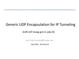
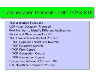
IP-UDP-RTP. Computer Networking (In Chap 3, 4, 7). 건국대학교 인터넷미디어공학부 임 창 훈. IP-UDP-RTP Packet. IP header. UDP header. RTP header. Application message. RTP packet. UDP packet (segment). IP packet (datagram). transport segment from sending to receiving host

E N D
IP-UDP-RTP Computer Networking (In Chap 3, 4, 7) 건국대학교 인터넷미디어공학부 임 창 훈
IP-UDP-RTP Packet IP header UDP header RTP header Application message RTP packet UDP packet (segment) IP packet (datagram)
transport segment from sending to receiving host on sending side encapsulates segments into datagrams on receiving side, delivers segments to transport layer network layer protocols in every host, router Router examines header fields in all IP datagrams passing through it network data link physical network data link physical network data link physical network data link physical network data link physical network data link physical network data link physical network data link physical application transport network data link physical application transport network data link physical Network layer
Key Network-Layer Functions • forwarding: move packets from router’s input to appropriate router output • routing: determine route taken by packets from source to destination • Routing algorithms analogy: • routing: process of planning trip from source to destination • forwarding: process of getting through single interchange
routing algorithm local forwarding table header value output link 0100 0101 0111 1001 3 2 2 1 value in arriving packet’s header 1 0111 2 3 Interplay between routing and forwarding
no call setup at network layer routers: no state about end-to-end connections no network-level concept of “connection” packets forwarded using destination host address packets between same source-dest pair may take different paths application transport network data link physical application transport network data link physical Datagram networks 1. Send data 2. Receive data
Forwarding table 4 billion possible entries Destination Address RangeLink Interface 11001000 00010111 00010000 00000000 through 0 11001000 00010111 00010111 11111111 11001000 00010111 00011000 00000000 through 1 11001000 00010111 00011000 11111111 11001000 00010111 00011001 00000000 through 2 11001000 00010111 00011111 11111111 otherwise 3
Longest prefix matching Prefix MatchLink Interface 11001000 00010111 00010 0 11001000 00010111 00011000 1 11001000 00010111 00011 2 otherwise 3 Examples Which interface? DA: 11001000 00010111 00010110 10100001 Which interface? DA: 11001000 00010111 00011000 10101010
IP protocol version number 32 bits total datagram length (bytes) header length (bytes) type of service head. len ver length for fragmentation/ reassembly fragment offset “type” of data flgs 16-bit identifier max number remaining hops (decremented at each router) upper layer time to live Internet checksum 32 bit source IP address 32 bit destination IP address upper layer protocol to deliver payload to E.g. timestamp, record route taken, specify list of routers to visit. Options (if any) data (variable length, typically a TCP or UDP segment) IP datagram format how much overhead with TCP? • 20 bytes of TCP • 20 bytes of IP • = 40 bytes + app layer overhead
host part subnet part 11001000 0001011100010000 00000000 200.23.16.0/23 IP addressing: CIDR CIDR:Classless InterDomain Routing • subnet portion of address of arbitrary length • address format: a.b.c.d/x, where x is # bits in subnet portion of address
provide logical communication between app processes running on different hosts transport protocols run in end systems send side: breaks application messages into segments, passes to network layer receive side: reassembles segments into messages, passes to application layer more than one transport protocol available to apps Internet: TCP and UDP application transport network data link physical application transport network data link physical network data link physical network data link physical network data link physical network data link physical network data link physical logical end-end transport Transport services and protocols
network layer: logical communication between hosts transport layer: logical communication between processes relies on, enhances, network layer services Transport vs. network layer
reliable, in-order delivery (TCP) congestion control flow control connection setup unreliable, unordered delivery: UDP no-frills extension of “best-effort” IP services not available: delay guarantees bandwidth guarantees application transport network data link physical application transport network data link physical network data link physical network data link physical network data link physical network data link physical network data link physical logical end-end transport Internet transport-layer protocols
application application application transport transport transport P4 P2 P1 P1 P3 network network network link link link physical physical physical Multiplexing at send host: Demultiplexing at rcv host: host 3 host 2 host 1 Multiplexing/demultiplexing delivering received segments to correct socket gathering data from multiple sockets, enveloping data with header (later used for demultiplexing) = socket = process
host receives IP datagrams each datagram has source IP address, destination IP address each datagram carries 1 transport-layer segment each segment has source, destination port number host uses IP addresses & port numbers to direct segment to appropriate socket How demultiplexing works 32 bits source port # dest port # other header fields application data (message) TCP/UDP segment format
“no frills,” “bare bones” Internet transport protocol “best effort” service, UDP segments may be: lost delivered out of order to app connectionless: no handshaking between UDP sender, receiver each UDP segment handled independently of others Why is there a UDP? no connection establishment (which can add delay) simple: no connection state at sender, receiver small segment header no congestion control: UDP can blast away as fast as desired UDP: User Datagram Protocol [RFC 768]
often used for streaming multimedia apps loss tolerant rate sensitive reliable transfer over UDP: add reliability at application layer application-specific error recovery! UDP: more 32 bits source port # dest port # Length, in bytes of UDP segment, including header checksum length Application data (message) UDP segment format
RTP runs on top of UDP • RTP libraries provide a transport-layer interface • that extend UDP: • port numbers, IP addresses • payload type identification • packet sequence numbering • time-stamping