Download
1 / 10
100 likes | 205 Views
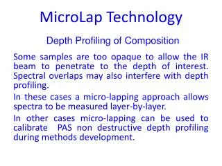
Depth Profiling of Composition. MicroLap Technology. Some samples are too opaque to allow the IR beam to penetrate to the depth of interest. Spectral overlaps may also interfere with depth profiling. In these cases a micro-lapping approach allows spectra to be measured layer-by-layer.

E N D
Depth Profiling of Composition MicroLap Technology Some samples are too opaque to allow the IR beam to penetrate to the depth of interest. Spectral overlaps may also interfere with depth profiling. In these cases a micro-lapping approach allows spectra to be measured layer-by-layer. In other cases micro-lapping can be used to calibrate PAS non destructive depth profiling during methods development.
Depth Profiling Using the MicroLap Process 4. Repeat layer by Layer 1. Measure Thickness 3. Lap off a Layer 2. Measure Spectrum
Lapping Puck Ball Joint Puck Adhesive Sample Polymer Layers or Gradient Lapped Surface 10 mm
Lapper Motion Oscillating Lapper Arm Blow-off Jet Rotating Puck Loading Mass Ball Joint Rotating Micro-Abrasive Timer
Successive Spectra Measured as a Function of Depth Transition EVOH PolyProp PolyProp 0 10 20 30 40 50 60 70 80
PAS Analysis of Composite Scorching Scorching occurs when jet exhaust strikes nearby aircraft (navy carrier decks). Carbon fiber/BMI panel scorched with air stream at 617 °C for 15 seconds. No visible change. PA spectra taken as material removed by microlapping.
Peak Height Ratios versus Depth into Scorch Damaged Transition Undamaged
Additional Information Can Be Foundin the MTEC Applications Library: Microlap Depth Profiling of a Paper Coating MicroLap Depth Profiling of Automobile Paint Weathering Quantitative Depth Profiling Saturation-Equalized Photoacoustic Spectra