Download
1 / 12
150 likes | 376 Views
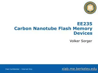
EE235 Carbon Nanotube FET. Volker Sorger. CNT-FET. SBFET. gate. source. drain. Gate. metal. metal. i or p -. 8nm HfO 2. Pd. Pd. CNT. SiO 2. p++ Si. Schottky Barrier (SB) CNT FET Transistor. “Carbon nanotubes as Schottky barrier transistors”

E N D
EE235Carbon Nanotube FET Volker Sorger
SBFET gate source drain Gate metal metal ior p- 8nm HfO2 Pd Pd CNT SiO2 p++ Si Schottky Barrier (SB) CNT FET Transistor “Carbon nanotubes as Schottky barrier transistors” Heinze et al., PRL, 89, 106801, 2002 Appenzeller et al., PRL, 89, 126801, 2002 Javey, et al., Nano Letters, 4, 1319, 2004 Tunneling limited current. Gate electrostatics will control the tunneling barrier.
MOS CNT FET Transistor MOSFET gate source drain n+ n+ ior p- Appenzeller et al., IEDM, 2004 Javey et al., Nano Letters, 5,2, 2005 Electrons do not see any tunneling barrier in the “on” state. Gate electrostatics control the top-of-the-barrier.
COXIDE CSEMI CNTs: Best Case Scenario Current Capacitance Physics: Low DOS makes band pinning difficult. Intuitively: Not enough electrons to screen the gate E-field. Circuits: COXIDE >~ CSEMI CNT array FET Iper tube ~ VDD/ 6.5Kohms ~150uA (@VDD = 1V) Take d = S = 1nm; Iper gate width ~ 500 X 150uA/um ~ 75mA/um (+non-idealities) Isilicon ~ 1mA/um Cper tube <~ 1-5 aF (@Length=50nm) Cper gate width ~ 500 X 2aF/um ~ 1fF/um Csilicon ~ 1fF/um Cinterconnect ~ 0.3fF/um (does not scale) C (per unit micron of width) = 1X I (per unit micron of width) = 50X TDELAY (for same transistor width) = 0.02X
Fs Fs Fs Ec Ec Ef Ef Ef Ev Ev P-type intrinsic N-type Work function Engineering for SB-FETs Work function: 5.12eV 4.33eV ~3.9eV Ec Ev What device can we built with this finding now?! M. H. Yang, W. I. Milne, APL, 2005
1-D Device Basics • What we want! • High Ion speed • Low Ioff less leakage • Steep switching small Subthreshold swing, SS • High mobility, m • How can we archive this? • Ion: Ohmic contacts + big tube • Ioff: high quality tox, small tube • SS: good gate coupling = small tox =4pF/cm
Intrinsic Gate Delay CV/I for PMOS R. Chau, IEEE Nanotechnology, 2005
Conclusion • CNT have potential • Devices can keep up with state-of-the-art Si • Still 3 major challenges to overcome (Integration) ~~~ Thank you for you attention ~~~
CNT-FET Benchmarking • Intrinsic Speed: CV/I vs. Lg • SS vs. Lg • Speed vs. Ion/Ioff • Metrology • I=Ion (@ Vg = Vt + 2/3 VDS) • I=Ion (@ Vg = Vt – 1/3 VDS) • V=Vcc=Vg=|VDS| • Device width = 2R • Vt from standard peak conductance R. Chau, IEEE Nanotechnology, 2005