Download
1 / 51
510 likes | 610 Views
CASK Design Meeting. DTS – Gregg Scharfstein VBA – Randy Hammond ICX – Stephen Smee. D FM T RANSPORT S TAGE Transport Cable Management Alignment. DTS. Components of Transport Guideways Motion Actuation Telemetry System Requirements Total Travel = 70.75 in [1797mm]

E N D
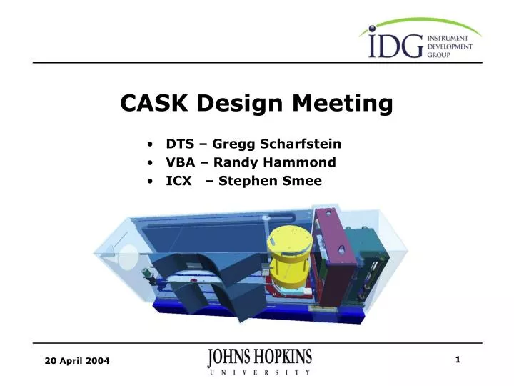
CASK Design Meeting • DTS – Gregg Scharfstein • VBA – Randy Hammond • ICX – Stephen Smee
DFM TRANSPORT STAGE Transport Cable Management Alignment DTS
Components of Transport Guideways Motion Actuation Telemetry System Requirements Total Travel = 70.75 in [1797mm] Full Travel in less than 30 seconds Positional Accuracy within .020 in [0.5mm] in all directions The Position of the DFM must be known at all times The DFM & DTS Motor shall be removable with relative ease Mechanisms shall be radiation hardened DTS: Transport
Thomson Accuglide Linear Guides Recess for alignment datum Four carriers interface Sled Standard Accuracy Class: within .004 in [.1 mm] in all directions over 79 in [2000 mm] travel DTS: Guideways
Thomson Precision Ball Screw Double Nut for anti-backlash Accuracy .004 in/ft [.33mm/m] Maximum Angular Velocity ~330 rpm (1000 rpm safe) DTS: Motion
Empire Magnetics Stepper Motor w/ CGI Planetary Right Angle Gear Head Motor Torque: 350 oz-in @ 1000 rpm (driving torque ~50 oz-in) 3:1 Ratio on gear head, capable of over 1200 in-lb Both units are radiation-hardened Inertia Ratio ~8, Torque Ratio ~21 DTS: Actuation
Absolute Position Data, Home Position & Limits Empire Magnetics Rad-Hardened Resovler with 160:1 Harmonic Drive Gear Head Magnetic Reed Switch @ Reference Position Honeywell GL Series Limit Switches Hard Stops located .1 in [2.5mm] past extreme travel DTS: Telemetry
Cabling Origins MACS-DFM Upper Bundle Lower Bundle DTS VBA DTS: Cable Management
Upper Bundle from MACS-DFM Bulkhead 2 Cables ~.5in [12.7mm] in diameter Replace current connector shell with 90-degree shells Rotary Take-up occurs on top surface of DFM Translation Take-up with Gortrac SS Cable Carrier DTS: Upper Bundle
Rotary Take-Up Quick disconnect strain relief Cable shroud keeps cable on top surface of DFM Bundle strain relieved before entering cable carrier DTS: Upper Bundle
Lower Bundle from MACS-DFM Bulkhead 8 Cables ~2in [51mm] in diameter Replace current bulkhead with Cable Guide Rotary Take-up occurs within Lower Shroud Translation Take-up with Gortrac SS Cable Carrier DTS: Lower Bundle
Rotary Take-Up Guide for cables out of DFM Blind-mate just after cable shroud Hard Stops DTS: Lower Bundle
Cables from DTS & VBA Cables run along channel in optical bench Join lower bundle and mate to Cask Bulkhead DTS: Lower Bundle
DTS: Alignment & Removal DTS Alignment & Removal • Optical Bench • DFM Interface Plate • DTS Motor
Optical Bench Alignment to MACS Bench sits on 3 pedestals Horizontal Plane Alignment: within .039 in [1 mm] Alignment Bar Vertical Plane Alignment: within .078 in [2 mm] Spec 1.4: mounting pad to beam centerline distance 817 +/- .2 mm Pedestals have tip/tilt adjustment DTS: Alignment & Removal
Optical Bench Alignment to MACS DTS: Alignment & Removal
Optical Bench Alignment to MACS DTS: Alignment & Removal
Optical Bench Installation & Removal Total Weight ~ 1300 lbs Lifting & Guide Poles installed without reaching into Cask Spreader attached to crane via Chain Sling w/ Turnbuckles Total height needed above floor for removal = 164” DTS: Alignment & Removal
Shielding Wall Installation & Removal Borated Poly Shielding Slab attached to 3/8” thick aluminum plate Contains guideway for upper cable carrier Constrained by guides attached to Cask Liner DTS: Alignment & Removal
DFM Interface Plate Alignment & Removal Lifting Brace Assembly & Guide Poles installed without reaching into Cask Tapered Guide Pins provide instrument-MACS alignment Blind Mate can be mated/de-mated without reaching into Cask DTS: Alignment & Removal
DTS Motor Removal & Installation Vertical installation & removal via pinion that interfaces planetary right angle gear head Captured Bolts allow mate/de-mate without reaching into Cask Slack in cable for motor allows retrieval and then connector de-mate DTS: Alignment & Removal
Conclusion DTS Status: • The DTS Design is 99% complete – Cask Bulkhead is the only remaining design task • Creating Fabrication Drawings is the next phase • Sub-Systems to be tested: • Rotary Cable Take-Up for Lower Bundle • Resolver Assembly for Absolute Position Information
MACS - Variable Beam Aperture The Variable Beam Aperture (VBA) shapes the MACS neutron beam to a variable rectangular cross section. VBA
Requirements • Ref: MACS Top Level Specification Revision D., Section 2.3 • Required: As Designed: • VBA Located ≤ 1500 mm from DFM reference 1445mm • Aperture Height and Width independently variable YES • Aperture not within line of sight of the sample YES • Aperture accommodates (passes) full beam diameter (355mm) YES • Shutters shall be 100mm thick YES • Shutters shall be composed of moderating and absorbing materials YES • Aperture shall be centered within 2mm of the DFM rot. axis TBD (easily achieved)
Design Overview • Dimensions • 500# Weight • 42.7in. (1085mm) height • 33.0in. (885mm) width • 8.9in. (225mm) depth • Aperture Range: 0.0 in to 14.25in (360mm) upstream • Major Features: • Chassis • Neutron Absorbing Shutters • Motive System / Bearings • Telemetry downstream
Chassis • The VBA Chassis is a bolted together aluminum structure: • Lift Points • Mounting Plate • Side Walls • Pedestal
Neutron Absorbing Shutters • There are two horizontal and two vertical shutters • Bolted together aluminum frame • Nominally 100mm thick along the beam axis • 2 degree draft angle on beam-side face • Composed of both moderating and absorbing components. • Assembly weighs 35#
Neutron Absorbing Shutters • Aluminum chassis includes stiffening web • 62mm upstream moderator (HDPE) • 5+mm B4C Moderator encapsulation limits scatter • 30mm downstream absorber (B4C)
Motive System / Bearings • Radiation Hardened Stepper Motors drive dual-handed leadscrews to position the shutters • Each shutter rides on all-steel twin ball bushings and hardened steel shafting. • Radiation hardened lubricants are used throughout.
Motive System / Bearings • Gimbaled lead nuts prevent binding • Nylon ring brushes exclude dirt and retain grease • Steel cap plates engage with threaded collars as full-open hardstop.
Motive System / Bearings • A test rig was developed to quantify shutter sag due to bearing slop and shaft bending • The majority of sag was determined to originate from shaft bending Ø1.25 shafting was selected for the bearing system FEA Predictions for Steel (42.5#) Shutter Assemblies
Motive System / Bearings VBA Operation
Telemetry • The VBA uses a conservative telemetry system • Positive sensing of VBA open and closed positions using rad-hard reed switches • Rad-hard absolute resolver assemblies used on both shutter pairs
Telemetry • Radiation Hardened Reed Switches are custom-prepared by Hermetic Switch, Inc. • 22ga. Kapton leads • Hermetic Switch supplied reed switch • Brass housing • 3M Polyurethane Potting • Samarium Cobalt Actuating Magnet
Component Status • Motors and Resolvers: ETA May 2004 • Harmonic Gear Heads: ETA June 2004 • B4C Panels: ETA May 2004 • HDPE Moderators: Complete • Machined Components: Drawings Underway
Conclusion • The MACS VBA is a mature mechanical design • Delivery on long lead items is expected within six weeks • Effort remains in: • Manufacturing Drawings • Cabling and wire routing details • Particulars of the mate with the optical bench • Absorbing material backfill
Inline Collimator Exhcanger The Inline Collimator Exchanger (ICX) provides four discrete collimation settings for the MACS experiment. ICX
Two co-aligned collimators: Segment-A: 60’ Segment-B: 40’ Segment A+B: 20’ 50 mm thick SS foils are coated with 13 mm Gd2O3 Collimators are exchanged using pneumatic actuators Adjustments integral to the guide bushing blocks facilitate co-alignment Weight ~ 300 lb ICX Lift Rods 10B:Al Stop Segment B Segment A Linear ball bushings
Details Type: Radial Collimation: 58.1’ Foil spacing: 3.3 mm at entrance Foil length: 135 mm Foil material: 50 mm stainless steel Foil coating: 13 mm Gd2O3 Number of foils: 97 Structural Material: 6061-T6 aluminum Mass: ~ 18 kg (40 lb) Clear aperture: 350 mm Segment A Note: design not representative of current tensioning scheme
Details Type: Radial Collimation: 41.0’ Foil spacing: 3.41 mm at entrance Foil length: 208 mm Foil material: 50 mm stainless steel Foil coating: 13 mm Gd2O3 Number of foils: 97 Structural Material: 6061-T6 aluminum Mass: ~ 27 kg (60 lb) Clear aperture: 350 mm Segment B Note: design not representative of current tensioning scheme
Details Type: radial co-aligned pair (Segments A and B) Collimation: 23.5’ Collimator separation: 8 mm foil to foil Transverse co-alignment: ± 0.05 mm RMS Angular co-alignment: ± 0.05 RMS Clear aperture: 350 mm Segment A+B
Flexures Flexure Adjustment Screws Adjustment Screws ICX Co-Alignment
Snap Ring Grease Retainer Linear Ball Bushing Adjustment Screws Bearing Block Detail
Misc. Details Upper Hard Stop Shim Alignment Cube Lower Hard Stop
Details Bimba 2” non-rotating cylinders, ~17” stroke Reed switches on cylinders for position sensing Hard stops internal to the ICX establish in-beam and stowed positions Cylinders can be replaced without entry into the cask ICX Lift Mechanism Pneumatic cylinders Lift Rods Liner
Cylinder Interface Details Clamp Ring Rod guide Cylinder Support O-Ring O-Ring
Cylinder Mount Detail Pneumatic Cylinder 1/4-20 Thread Shaft Clamp Support Tube
MACS Electrical System • ICX, DTS and VBA control will be added to a new drawer in the existing DFM Rack. • A PCI Digital I/O Card will be installed in the PC.
VBA Electrical System Resolver Readout Electronics RS422 Empire Magnetics RH-EMR-57 Resolver Magnetic Reed Switches MAX 410 Motor Indexer VBA Vert Empire Magnetics RH-U33-S Vert Motor +40V Motor Empire Magnetics RH-U33-S Horiz Motor +5V Logic MAX 410 Motor Indexer VBA Horiz Magnetic Reed Switches Empire Magnetics RH-EMR-57 Resolver
DTS Electrical System Resolver Readout Electronics RS422 Empire Magnetics RH-U33-S Motor MAX 410 Motor Indexer DTS Drive +40V Motor Reed Home Sensor +5V Logic Limit Switches Empire Magnetics RH-EMR-57 Resolver


![CASK [NOUN]](https://cdn1.slideserve.com/2754944/cask-noun-dt.jpg)