Download
1 / 54
540 likes | 651 Views
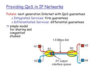
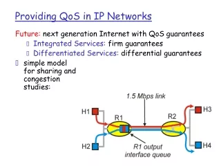
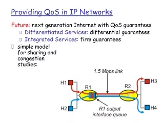
QoS in Converged Networks. ITK 477. QoS in PSTN. In traditional telephony, quality of service for each and every phone call is guaranteed by the constant availability of dedicated bandwidth.

E N D
QoS in Converged Networks ITK 477
QoS in PSTN • In traditional telephony, quality of service for each and every phone call is guaranteed by the constant availability of dedicated bandwidth. • Most digitally encoded call paths on the PSTN use the same codec, G.711, so transcoding isn’t necessary. • Almost no processing bottlenecks will be found on the PSTN, and since the system isn’t generally packet-based, there is almost never degradation in perceived call quality as a result of congestion.
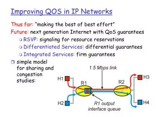
QoS in Packet Networks • When bandwidth availability drops, as more packets are sent on the network, throughput slows. • Until a certain breaking point, bandwidth availability can be compromised while still allowing data through; the transmission just slows down. • Some applications tolerate congestion and slow • throughput better than others. The more tolerance an application has, the higher its error budget is said to be.
Latency • Slowness of transmission—latency—is the enemy of multimedia traffic • Solution to the latency problem: technique that allows local and end-to-end guarantees of bandwidth and prioritization of real-time traffic over less sensitive traffic. • QoS protocols and standards: 802.1p, 802.1q VLAN, DiffServ, RSVP, and MPLS.
Call-quality scoring • Mean opinion score (MOS): Listeners hear sound samples from calls of varying quality, recorded during different sets of network conditions. • Everbody rates the sample’s quality on a scale of 1 to 5, with 5 being the best quality. • G.711’s highest perceived quality score is 4.4. By comparison, G.729A’s is only 3.6. • See next figure:
Don’t use G.729A across a fast Ethernet link because the quality perceived by users will be lower than it ought to be.
Noise • One of the biggest factors in perceived quality is noise. • Additive noise is the unwanted signals that accompany all transmissions of sound. Subtractive noise is an interruption or reduction of the sound transmission, such as that caused by packet loss.
Noise • Multimedia traffic, such as VoIP does introduce new kinds of noise, broadening the traditional definition to include everything shown in the next figure. • While noise cannot be entirely avoided, it should be minimized. • One of QoS’s roles is to help us avoid situations in which poor service at the lower layers of the network results in additive or subtractive noise.
Latency, Packet Loss, and Jitter • Latency (also called lag) is caused primarily by slow network links. • End-to-end latency, in the case of VoIP, is the time it takes from the instant the caller utters something until the time the receiver hears that utterance. • Round-trip latency less than 150 ms is not immediately noticeable, but latency higher than 150 ms is discouraged, and latency higher than 300 ms is considered unacceptable. • Latency has the following effects on telephony and video applications: • Can slow down the human conversation • Can result in caller and receiver unintentionally interrupting each other • Can worsen another Quality-of-Service problem: echo • Can cause synchronization delays in conference-calling applications The best ways to beat latency are to use low-packet-interval codecs and maintain fast network links, because QoS protocols alone cannot directly improve latency’s impact. That is, they can’t speed up your network.
Sources of Latency • Framing and packetization • • Software processing and packet loss concealment (PLC; replacing the sound that would presumably have been produced by a packet that was lost with sound that is predicted based on the sequence of packets received before it and (when extensive buffering is used) after it) • Jitter buffering • Routing and firewall traversal • Transcoding • Media access and network interfacing Minimizing latency is an important way to maximize the multimedia (VOIP) network’s perceived quality of service.
Cont. • The two biggest sources of latency are framing/packetization, which can add up to 30 ms of latency, and routing, which can add 5–50 ms per hop. • Another big contributor is transcoding (See next figure)
Packet Loss • Even with PLC in force, packet loss rates on a VoIP network should be kept below 1%. • A drawback of PLC is that it can increase latency. • Experimentation with Packet Loss Concealment (PLC)-equipped codecs should be done to determine how negative the latency-impact PLC is in your VoIP network.
Jitter • It’s the variation in latency time from one packet to the next. • It causes packets to arrive out of order, leaving gaps in the framing sequence of the voice/video signal. • Jitter is at its worst when voice traffic must travel through several routers on the network. • Different routers, especially those at ISPs, may be configured to queue and forward different kinds of traffic in different ways. • Others may be loadbalancing, which can contribute to jitter. • The main goal of QoS protocols is to eliminate jitter. • Devices called jitter buffers, in endpoints and VoIP servers, can minimize the effect of jitter, too. But, like PLC measures, they do so by increasing latency.
Class of Service (COS) • CoS systems work to prioritize traffic on a single data link. • While QoS refers to the greater network, CoS refers to only a single data link. • The key difference is that CoS is a single-link approach, while QoS is an end-to-end approach. • Class of Service systems define per-hop behavior, so they cannot guarantee a service • level in terms of capacity or speed. • Two key standards support CoS: 802.1p/ToS DiffServ
802.1p • 802.1p uses a 3-bit portion of the Ethernet packet header to classify each packet into • a particular level of precedence on the local data link. • Type of Service (ToS) is the portion of the IP packet header that stores the same precedence information. • If your VoIP network will be more than 70% data-to-voice and unlikely to reach capacity, packet prioritization techniques like LAN-oriented 802.1p and its WAN cousin DiffServ are adequate. • The next table lists the suggested, generic service names.
Differentiated Services (DiffServ). . When a packet reaches the edge of the network, either from an endpoint or from a • remote network, DiffServ tags that packet’s ToS header based on the priority established for that packet by policy. • Once admitted into a DiffServ-equipped WAN, however, all subsequent router hops must enforce the priority set by the edge router that admitted the packet.
Policy servers • Common Open Policy Service, or COPS, is a way of storing and querying centralized • policy information on the network. • DiffServ can use COPS to obtain its marching orders for how to handle traffic coming into the network. • In a COPS scheme, a centralized server called the policy server contains a policy record of traffic shaping and prioritization preferences that DiffServ or another CoS/QoS mechanism can retrieve. • Another IETF recommendation, LDAP (Lightweight Directory Access Protocol), can also be used as the basis of a policy server.
DiffServ Code Points (DSCP) • DSCP classes are IP packet headers DiffServ associates with different levels of importance. • Since they’re 6 bits in length, DSCPs can be used to define quite a wide scale of possible service levels. Most implementations support only 3 bits, replacing the 3 bits in IP’s ToS header. • DSCP per-hop behaviors break down into three basic groups, interchangeably called PHB classes, traffic classes, or DSCP classes:
DSCP Classes • AF Assured Forwarding, a highly expedient DSCP class, sometimes used to tag signaling packets such as H.245/H.225 and SIP packets. • EF Expedited Forwarding, the most expedient DSCP class, used to tag packets carrying actual sound data. • BE Best Effort, a nonexpedient DSCP class, used to tag non-voice packets. Many DiffServ decision points don’t use BE.
802.1q VLAN • Broadcast domain per network segment means that when a packet comes across the segment destined for a local host whose hardware (MAC) address has not yet been resolved (ARPed) and associated with a certain switch port on the Ethernet segment, a broadcast to all ports is done in order to find a host with the right MAC address that’s supposed to receive the packet. • Once the port with the correct recipient is found, an ARP record is recorded in the switch so that all future traffic destined for that MAC address can go to that port rather than being broadcast. • One problem is that the broadcast traffic can be a waste of bandwidth. • Another problem is that, when broadcasts occur, every device on the network can receive them, which is a potential security hazard. • 802.1q VLAN (virtual LAN) is a way to separate Ethernet traffic logically, secure Ethernet broadcast domains, organize the network by separating network protocols into their own VLANs • Each VLAN is a logically separate broadcast domain—even if it coexists with other VLANs on the same physical segment.
Layer 2 Switching • With most vendors’ Ethernet equipment, to create VLANs, each switch port is assigned a VLAN tag—a numeric identifier that is unique within the network. • This tag identifies the VLAN in which that port participates. Once the tag is assigned, the device connected to that port will receive traffic only from the assigned VLAN and will be able to send traffic only to the assigned VLAN.
Layer 3 Switching • Sometimes Ethernet switches can be used to groom, inspect, or route traffic. • Layer 3 switching accomplishes some router-like activities: queuing, routing, and packet-inspection. • It can be used to shape the traffic on the data link based on each packet’s • characteristics. • For example, it’s possible to drop all non-voice traffic by filtering protocol types (UDP, TCP, etc.) and port numbers.
Quality of Service • Intserv (Integrated Services) is an IETF recommendation for provided dedicated bandwidth to individual flows, or media channels, on an IP network. • The media channels are referred to by their sockets • RSVP (Resource Reservation Protocol) is the recommended signaling protocol for • Intserv. • The purpose of RSVP is to ensure that the network has enough bandwidth to support • each call, before any data is passed through the media channel. • RSVP adds decision-making points to the core network, increasing the processing overhead requirement on core routers. • RSVP is the perfect solution for bandwidth allocation over slower links, because it guarantees availability for each RTP stream, rather than giving a “best effort.”
H.323 1. H.245 negotiates the codec and establishes RTP sockets that will be used on either end of the media channel. These two sockets—the IP addresses and port numbers—together form the session ID that RSVP will use to refer to this RTPsession. RSVP calls the session ID a flow ID. 2. The gateway router for the caller, B, sends a path message (PM) to the next hop, B, along the way to the remote gateway router, D. This PM will continue to be forwarded from one hop to the next in order to establish the QoS path. 3. B records the latency added as the PM reaches it, along with minimum latency, jitter ranges the router is willing to guarantee. Then, the PM is sent to the next router along the path, in this case, C. 4. C records the latency added as the PM reaches it, along with minimum latency, jitter ranges the router is willing to guarantee. Then, the PM is sent to the next router along the path, in this case, D. 5. When the PM reaches the remote gateway router, D, cumulative latency and jitter are calculated. The result is a profile call the ADSPEC, and the portion of the RSVP header used to accumulate QoS data during the PM is called the ADSPEC header.
Link delays and maximum jitter readings are recorded for each hop.
RSVP • When the remote gateway router reads the ADSPEC data and makes the determination, it can do one of two things: • Give up, resulting in a busy tone for the caller, or • Trigger the reserve message (RM) to set up the traffic contracts with each router in order to reserve bandwidth for the call.
Reserve Messages (RM) 1. The remote gateway router (D) sends the reserve message to the previous router in the path. The sender and receiver RTP sockets are confirmed, and a contract is established for the timeout value in seconds, sustained throughput, and peak throughput required by the RTP session. 2. The previous router in the path (C) sends a similar RM to its previous router in the path (B). 3. Router B sends router A another RM.
RM Confirmation 1. Router A sends a reserve confirm message to router B if it agrees to guarantee the bandwidth and timeout values requested, or a rejection message if not. 2. Router B sends router C a similar response. If the first response, from router A, was a rejection, then all subsequent responses will be rejections as well. 3. Router C sends router D a similar response. If the first or second was a rejection, then this response will be a rejection as well.
RSVP Service Levels • RSVP defines three service levels in RFC 2211: • Best Effort A class of service that has no QoS measures whatsoever. On Cisco routers, the fair-queuing feature is used to enable Best Effort service. • Controlled Load Allows prioritization of traffic over multiple routers like DiffServ but includes core routers in the decision-making process. • Guaranteed No packets will be lost, bandwidth will be constant, and delay will be within the prescribed ranges set up in the traffic contract.
MPLS • MPLS bears great similarity to ATM signaling but borrows heavily from RSVP. Unlike ATM, which incurs a 25% overhead on TCP/IP traffic (called the ATM “cell tax”), MPLS doesn’t use its own framing format, just its own labeling format. • The purpose of MPLS labels is to identify the paths and priorities associated with each packet. The paths correspond to the media channel of the VoIP call, while the priorities respond to the QoS level of service negotiated for those channels, just like RSVP. • But like DiffServ, MPLS can use a dumb network core. If a packet is carrying a label, all a router has to do is send it along the labeled path, rather than making a redundant assessment of the packet’s payload. • MPLS inserts itself partially in layer 2 and partially in layer 3 on the OSI model. Its frame header sits between the IP header and the Ethernet header on an Ethernet network or between the label header and the payload on an ATM network. • What’s important to know is this: MPLS resides outside the reach of the network protocol, like 802.1p. framing protocol (Ethernet framing, for example). This makes it invisible to the higher layers.
Multiprotocol Label Switching (Handout) • Multiprotocol Label Switching (MPLS) • Born of Cisco’s tag switching, designed with large-scale WAN in mind, MPLS was proposed by the Internet Engineering Task Force (IETF) in 1997. • Core specifications for MPLS were completed by IETF in the fall of 2000. • By plotting static paths through an IP network, MPLS gives service providers the traffic engineering capability they require while also building a natural foundation for VPNs. • Traffic engineering allows service providers to do two things: control quality of service (QoS) and optimize network resource utilization. • MPLS also has the potential to unite IP and optical switching under one route-provisioning umbrella.
How MPLS Works • “MP” means it is multiprotocol. MPLS is an encapsulating protocol, it can transport a multitude of other protocols. • “LS” indicates that the protocols being transported are encapsulated with a label that is swapped at each hop. • A label is a number that uniquely identifies a set of data flows on a particular link or within a particular logical link. • The labels are of local significance only – they must change as packets follow a path – hence the “switching” part of MPLS.
How MPLS Works • MPLS can switch a frame from any kind of layer-2 link to any other kind of layer-2 link without depending on any particular control protocol. • ATM can only switch to and from ATM and can use only ATM signaling protocols, such as PNNI (Private Network-to-Network Interface) and IISP (Interim Interface Signaling Protocol).
MPLS • Since IP is a connectionless protocol, it cannot guarantee that network resources will be available. • Additionally, IP sends all traffic between the same two points over the same route. During busy periods, therefore, some routes get congested while others remain underutilized. • One key difference between MPLS and IP is that packets sent between two end points can take different paths, based on different MPLS labels. • Without explicit control over route assignments, the provider has no way to steer excess traffic over less busy routes.
MPLS • MPLS tags or adds a label to IP packets so they can be steered over the Internet along predefined routes. • MPLS also adds a label identifying the type of traffic, path and destination. • This allows routers to assign explicit paths to various classes of traffic. • Using explicit routes, service providers can reserve network resources for high-priority or delay-sensitive flows, distribute traffic to prevent network hot spots and pre-provision backup routes for quick recover from outages.
MPLS • An MPLS network is comprised of a mesh of label switch routers (LSRs) • LSRs are MPLS-enabled routers and/or MPLS-enabled ATM switches. • As each packet enters the network, an ingress LSR assigns it a label based on its destination, VPN membership, type-of-service bits, etc. • At each hop, an LSR uses the label to index a forwarding table. The forwarding table assigns each packet a new label, and directs the packet to an output port. To promote scaling, labels have only local significance • As a result, all packet with the same label follow the same label switched path (LSPs) through the network.
Multiprotocol Label Switching (Stallings, High-Speed Networks)
How MPLS Works • With MPLS you can support all applications on an IP network without having to run large subsets of the network with completely different transport mechanisms, routing protocols, and addressing plans. • Offers the advantages of circuit-switching technology, including bandwidth reservation and minimized delay variations for voice and video traffic, plus all the advantages of existing best-effort, hop-by-hop routing. • Allows service providers to create VPNs with the flexibility of IP but the QoS of ATM.
MPLS Labels • MPLS supports three different types of label formats. • On ATM hardware it uses the well-defined Virtual Channel Identifier (VCI) and Virtual Path Identifier (VPI) labels. • On frame relay hardware, it uses a Data Link Connection Identifier (DLCI) label. • Elsewhere, MPLS uses a new, generic label known as a Shim, which sits between layers 2 and 3. • Because MPLS allows the creation of new label formats without requiring change in routing protocols, extending technology to new optical transport and switching should be straightforward.
MPLS Label Stacking • Another powerful attribute of MPLS is Label Stacking. • Label stacking allows LSRs (label switched router) to insert an additional label at the front of each labeled packet, creating an encapsulated tunnel that can be shared by multiple LSPs (label switched paths). • At the end of the tunnel, another LSR pops the label stack, revealing the inner label. • An optimization in which the next-to-last LSR peels off the outer label is known in IETF documents as “penultimate hop popping”.
MPLS Label Stacking • ATM has only one level of stacking, virtual channels inside of virtual paths. • MPLS supports unlimited stacking. • An enterprise could use label stacking to aggregate multiple flows of its own traffic before passing it on to the access provider • The access provider could aggregate traffic from multiple enterprises before handing it to a backbone provider • The backbone provider could aggregate traffic yet again before passing it off to a wholesale carrier.
MPLS Label Stacking • Service providers could use label stacking to merge hundreds of thousands of LSPs into a relatively small number of backbone tunnels between points of presence. • Fewer tunnels means smaller route tables, making it easier for providers to scale the network core.