Download
1 / 10
110 likes | 307 Views
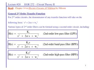
Lecture #20 EGR 272 – Circuit Theory II. Read : Chapter 14 in Electric Circuits, 6 th Edition by Nilsson. General 2 nd Order Transfer Function For 2 nd order circuits, the denominator of any transfer function will take on the following form: s 2 + 2 s + w o 2

E N D
Lecture #20 EGR 272 – Circuit Theory II Read: Chapter 14 in Electric Circuits, 6th Edition by Nilsson General 2nd Order Transfer Function For 2nd order circuits, the denominator of any transfer function will take on the following form: s2 + 2s + wo2 Various types of 2nd order filters can be formed using a second order circuit, including:
Lecture #20 EGR 272 – Circuit Theory II Series RLC Circuit (2nd Order Circuit) Draw a series RLC circuit and find transfer functions for LPF, BPF, and HPF. Note that the denominator is the same in each case (s2 + 2s + wo2). Also show that:
Lecture #20 EGR 272 – Circuit Theory II Parallel RLC Circuit (2nd Order Circuit) Draw a parallel RLC circuit and find transfer functions for LPF, BPF, and HPF. Note that the denominator is the same in each case (s2 + 2s + wo2). Also show that:
Lecture #20 EGR 272 – Circuit Theory II 2nd Order Bandpass Filter A 2nd order BPF will now be examined in more detail. The transfer function, H(s), will have the following form: • Magnitude response • Show a general sketch of the magnitude response for H(s) above • Define wo , wc1 , wc2 , Hmax , BW, and Q • Sketch the magnitude response for various values of Q (in general)
Lecture #20 EGR 272 – Circuit Theory II Determining Hmax Find H(jw) and then H(jw). Show that
Lecture #20 EGR 272 – Circuit Theory II Determining wc1 and wc2 : leads to Show that
Lecture #20 EGR 272 – Circuit Theory II Determining wo, BW, and Q: Show that wo is the geometric mean of the cutoff frequencies, not the arithmetic mean. Also find BW and Q. Specifically, show that: Damping ratio is simply defined here. Its significance will be seen later in this course and in other courses (such as Control Theory). Circuits with similar values of z have similar types of responses.
Lecture #20 EGR 272 – Circuit Theory II Example: A parallel RLC circuit has components R, L = 100 mH, and C = 0.1 uF 1) Find wo , , Hmax , wc1 , wc2 , Hmax , BW, Q, and z 2) Show that wo is the geometric mean of the wc1 and wc2 , not the arithmetic mean. A) Use R = 1 kW
Lecture #20 EGR 272 – Circuit Theory II Example: A parallel RLC circuit has components R, L = 100 mH, and C = 0.1 uF 1) Find wo , , Hmax , wc1 , wc2 , Hmax , BW, Q, and z 2) Show that wo is the geometric mean of the wc1 and wc2 , not the arithmetic mean. B) Use R 20 kW
|H(jw)| 5k 6k 7k 8k 9k 10k 20k w (log scale) Lecture #20 EGR 272 – Circuit Theory II Example: Plot the magnitude response, |H(jw)|, for parts A and B in the last example. (Note that a curve with a geometric mean will appear symmetrical on a log scale and a curve with an arithmetic mean will appear symmetrical on a linear scale.)


