Download
1 / 27
270 likes | 367 Views
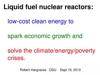
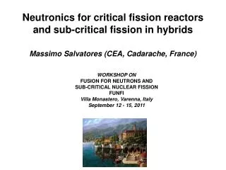
Fuel cycles and envisioned roles of fast neutron reactors and hybrids M.Salvatores (CEA, Cadarache- France). WORKSHOP ON FUSION FOR NEUTRONS AND SUB-CRITICAL NUCLEAR FISSION FUNFI Villa Monastero, Varenna, Italy September 12 - 15, 2011. Nuclear Fuel Cycles.

E N D
Fuel cycles and envisioned roles of fast neutron reactors and hybrids M.Salvatores (CEA, Cadarache- France) WORKSHOP ON FUSION FOR NEUTRONS AND SUB-CRITICAL NUCLEAR FISSION FUNFI Villa Monastero, Varenna, Italy September 12 - 15, 2011
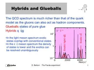
Nuclear Fuel Cycles • Many of the central issues associated with nuclear power are tied primarily to thechoice of fuel cycle. Resource limitations, non-proliferation, and waste management areprimarily fuel cycle issues. • The fuel cycle provides the mass flow infrastructure thatconnects the energy resources of uranium and thorium ore through the nuclear powerplants to the eventual waste management of the nuclear energy enterprise. • Natural resources include fuels (uranium and thorium), materials of construction, andrenewable resources (such as water for cooling purposes). Wastes may include milltailings, depleted uranium, spent nuclear fuel (SNF) and high level (radioactive) waste(HLW), other radioactive wastes, releases to the environment (air and water), and nonnuclearwastes. • Multiple technical facilities are deployed in the fuel cycle. In a simplified fuel cycleschematic, there are 7 major fuel cycle facilities.
3 4 5 2 6 7 11 1
The preferred choice or choices of fuel cycles and reactors depends upon the requirements for sustainability, safety, and economics . Four generic fuel cycles span the space of feasibleconversion of ore resources to energy. • Once through. The fuel is fabricated from uranium (and/or thorium),irradiated, and stored to allow for reduction of heat, then directly disposed of as a waste. Light Water Reactors(LWRs) in the United States currently use this fuel cycle. • Partial recycle. Some fraction of the SNF is processed, and some fraction of the actinide material is recovered from recycle, and new fuel is fabricated. The fuel is returned to the reactor one-two times
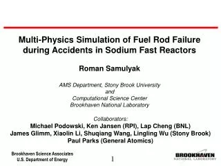
• Full fissile recycle. All SNF is processed for recovery and recycle ofplutonium (and/or 233U). The SNF is repeatedly processed and recycled.Minor actinides and fission products are sent to the waste stream from theprocessing operation. An example of this is the traditional Liquid MetalFast Breeder Reactor (LMFBR) fuel cycle. • Full-actinide recycle. All SNF is processed, and all actinides are multiplyrecycled. An example of such afuel cycle is a system of MOX-LWRs anddedicated burner reactors. The MOX-LWRs produce power and the dedicated burner reactors (e.g. ADS, Hybrid fission-fusion, critical fast reactors) are used to destroy higher actinides thatwould otherwise be sent to the repository. Another example is the full TRU multiple recycle in FRs, both to extend use of resources and to reduce and stabilize wastes. • Other fuel cycle options are envisaged according to e.g. waste management strategies
Pu Fuel Fabrication Reprocessing Pu Multi-recycling MOX-LWR (or FR) UOX-PWR Repository FP and TRU losses at reprocessing Irradiated fuel FP and TRU losses at reprocessing Irradiated fuel FP and TRU losses at reprocessing Reprocessing Dedicated Transmuter Reprocessing MA (+Pu) Multi-recycling MA (+Pu) Fuel Fabrication MA(+Pu) Irradiated fuel Full-actinide recycle (So-called “Double Strata Fuel Cycle”) MA
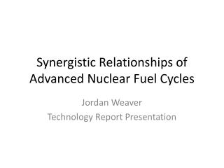
Repository UOX-LWR FP and TRU losses at reprocessing Irradiated fuel FP and TRU losses at reprocessing Irradiated fuel Reprocessing Reprocessing Pu+MA Pu+MA Full-actinide recycle (FR only)
Fuel cycle simulation allows the calculation of the nuclei evolution under irradiation and decay outside the reactor (the Bateman equations) • Once the nuclei evolution has been performed, it is possible to evaluate all the derived quantities: nuclei mass inventories, decay heat, neutron sources, radiotoxicity, doses etc
Nuclei evolution under irradiation The Uranium nuclei transmutation chain under neutron irradiation and the associated Bateman equations can be represented as follows: Bateman equations where nj is the nuclide j density, σaj is the absorption cross section of isotope j, σjk is the cross section corresponding to the production of isotope j from isotope k, λj is the decay constant for isotope j, λjk is the decay constant for the decay of isotope k to isotope j and, finally, Φ is the neutron flux.
Application Composition of Spent Nuclear Fuel (Standard PWR 33GW/t, 10 yr. cooling) 1 tonne of SNF contains: 955.4 kg U 8,5 kg Pu Minor Actinides (MAs) 0,5 kg 237Np 0,6 kg Am 0,02 kg Cm Long-Lived fission Products (LLFPs) 0,2 kg 129I 0,8 kg 99Tc 0,7 kg 93Zr 0,3 kg 135Cs Short-Lived fission products (SLFPs) 1 kg 137Cs 0,7 kg 90Sr Stable Isotopes 10,1 kg Lanthanides 21,8 kg other stable Most of the hazard stems from Pu, MA and some LLFP when released into the environment, and their disposal requires isolation in stable deep geological formations. A measure of the hazard is provided by the radiotoxicity arising from their radioactive nature.
Most of the derived quantities are of the type: • where ni is the nuclei i density and hi are coefficients, specific for each application Example: the Radiotoxicity R of nuclei i is given by: Ri(Sievert)= Fi(Sv/Bq)xAi(Bq) where F is a Dose Factor (ingestion or inhalation) and A is activity in Bq Total activityA: number of decays an object undergoes per second. Decay constant λ: the inverse of the mean lifetime. One has: Finally: Ri(Sievert)= Fi(Sv/Bq)xAi(Bq) =Fi xniλi
Derived quantities: the radiotoxicity Evolution of the radiotoxic inventory, expressed in sievert per tonne of initial heavy metal (uranium) (Sv/ihmt) of UOX spent fuel unloaded at 60 GW d/t, versus time (years).
Derived quantities: the decay heat, one of the most demanding parameters of the fuel cycle
Decay Heat Components Fuel Cycle Modelling
Decay heat: relative role of FPs and Actinides for standard LWR fuel Actinides FP Long cooling times Short cooling times
Decay heat: FPs and Actinides components for standard LWR fuel FP Total TRU Am-241 Pu-238
Derived quantities and the impact of different fuel cycle scenarios • The full TRU recycle, as indicated previously, allows a significant reduction of the radiotoxicity and of the decay heat of residual wastes to be sent to the repository. • This reduction can have a favorable impact in the assessment of future fuel cycles • This result is true within both scenarios for full TRU recycle indicated above.
MA + FP Pu + MA + FP Plutonium recycling Spent Fuel Direct disposal Relative radiotoxicity Uranium Ore (mine) P&T of MA FP Time (years) Example: Impact of the actinides management strategy on the radiotoxicity of ultimate waste Recycle of all actinides from spent LWR fuel in fast reactors provides a significant reduction in the time required for radiotoxicity to decrease to that of the original natural uranium ore used for the LWR fuel: From 250,000 years down to about 400 years, if 0.1% TRU loss to wastes during reprocessing.
Pu + MA + FP Spentfueldirectdisposal Example: Impact of the actinides management strategy on the decay heat of ultimate waste MA + FP FP
An Example of Scenario Study Hypotheses and assumptions In the selected scenario study two groups of nations are considered: • the first one with a stagnant or phasing-out nuclear policy (Group A) • the second with an ongoing nuclear power development (Group B) The final goals of the scenario are: - to reduce Group A TRU inventory down to zero till the end of the century; - to stabilize Group B MA inventory and to save reprocessed Pu in order to allow a later introduction of fast reactors for nuclear power generation. In the fuel cycle transmuters first use MA coming from their closed cycle (in order to completely transmute heavy nuclides), then those of Group A, and finally those of Group B.
Three types of transmuters have been compared: • The SABR fusion-fission hybrid concept is a sodium cooled sub-critical fast reactor driven by a D-T fusion neutron source; • ADS-EFIT is Pb cooled and the external neutron source is provided by Pb-proton (800 MeV) spallation reaction on a Pb windowless target; • LCFR is a Na cooled critical fast reactor with a conversion ratio ~0.5 • The scenario is of the “Double Strata” type, as described previuosly
Scenario Flow Sheet Group A: Belgium, Czech Republic, Germany, Spain, Sweden and Switzerland Group B: France Regional (i.e. shared) facilities (i.e. transmuters, fuel fabrication, reprocessing facilities and stocks) operation start-up is assumed to be in 2045.
Required Transmuters Energy Production - Comparison is presented per energy produced - The corresponding number of units are 13 (X384 MWth) ADS-EFITs, 9 (X1000 MWth) LCFRs, and 2 (X3000 MWth) SABRs - As expected, more critical low conversion ratio transmuters are needed since they achieve ~70% of the max theoretical burning rate (i.e. when no U in the fuel)
MA Stocks Comparison - MA stock of Group A goes to zero before the end of the century (in all cases) - MA stock of Group B is stabilized before the end of present century (in all cases)
Fuel Cycle Impacts Radiotoxicity and heat load in a repository are reduced by two orders of magnitude with respect to the direct disposal scenario
• Uranium and thorium mills. Uranium and thorium ores are mined andthen milled to extract uranium and thorium. This process generates the highest volumewaste stream in the fuel cycle: mill tailings. Also, purification and conversion facilities. • Uranium enrichment. The uranium is isotopicallyseparated into a stream enriched in the fissile isotope 235U and a streamdepleted in the fissile isotope 235U. The enriched stream is used for fuel inmost reactors. The depleted uranium may be stored for (1) furtherrecovery of 235U in the future or (2) use in fast neutronreactors. Alternatively, it may become a waste. • Fuel fabrication. Reactor fuel is fabricated from natural uranium, enriched uranium, plutonium reclaimed from processingdischarged fuel, or uranium-233, depleted uranium, and thorium. • Reactor. The reactor produces energy and SNF. • Spent Nuclear Fuel Storage. The SNF is stored toallow its radioactivity and heat release rate to decrease. After storage, theSNF may be (1) considered a waste for disposal or (2) processed torecover fissile materials from the SNF for recycle back to the reactor asnew fuel. • Processing. If the SNF is recycled, the recovered fissile materials can be used to produce new fuel. • Waste disposal. SNF direct disposal or vitrification of residues from reprocessing