Download

1 / 21
260 likes | 361 Views
Failure of composites. John Summerscales. Outline of lecture. strength failure mechanisms fractography fracture mechanics failure criteria. Strength. strength = stress at failure failure may be yielding in metals non-recoverable loss of elastic response first-ply failure

E N D
Failure of composites John Summerscales
Outline of lecture strength failure mechanisms fractography fracture mechanics failure criteria
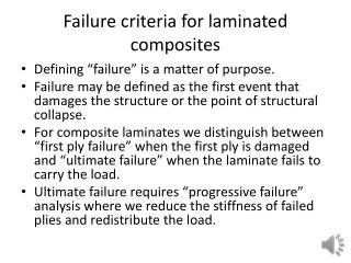
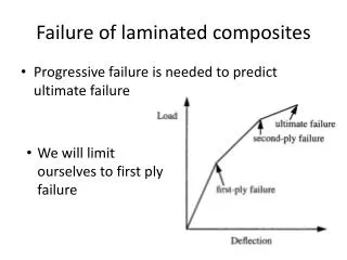
Strength • strength = stress at failure • failure may be • yielding in metals • non-recoverable loss of elastic response • first-ply failure • ultimate failure • one material can have several different strengths
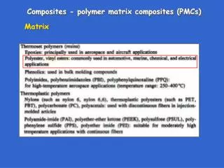
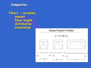
Strength • Kelly-Tyson equation for UD composites: • σc = σfVf + σm*(1-Vf) at high Vf, or • σc < σm#(1-Vf) at low Vf • where σm* is the tensile stress in the matrixat the failure strain of the fibre, and • σm# is the maximum tensile strength of the matrix • For small mis-alignments: • σc = σfVf / cos2θ = σfVfsec2θ
Failure mechanisms • matrix cracking • fibre fracture • debonding = interface failure • delamination = interlayer failure • fibre pullout • micro-buckling • kink bands • cone of fracture
Failure strain of composites • The key criterion for composite failure is the local strain to failure: ε’ a.k.a. elongation at breakand not stress • Note that ε’ for the fibre/matrix interfacei.e. transverse fibres = ~0.25 %
Matrix cracking maxmin • polyester resin ε’ = 0.9-4.0 % • vinyl ester ε’ = 1.0-4.0 % • epoxy resin ε’ = 1.0-3.5 % • phenolic resin ε’ = 0.5-1.0 % • data from NL Hancox, Fibre Composite Hybrid Materials, Elsevier, 1981.
Fibre fracture • S/R-glass ε’ = 4.6-5.2 % …. • E-glass ε’ = 3.37 % ……….… • Kevlar 49 ε’ = 2.5 % ………………. • HS-carbon ε’ = 1.12 % ………………… • UHM-carbon ε’ = 0.38 % ………………….. • data from NL Hancox, Fibre Composite Hybrid Materials, Elsevier, 1981.
Fibre-matrix debonding • Crack can run • through (not shown), or • around the fibre • ~12000 carbon or 1600 glass UD fibres / 1 mm2 b a
Delamination of layers • one layer is a lamina (plural = laminae) • several layers in a composite is a laminate • separation of the layers is delamination • to avoid delamination • 3-D reinforcement (often woven or stitched) • vertically aligned carbon nano tubes (VACNT) • Z-pinning
Stress whitening of GFRP debonding (fibre/matrix separation) and delamination (layer separation)both create internal defectswhich scatter light the consequence is that the laminate changes from transparent to opaque,referred to as “stress whitening” similar effects may be seen in other composites (e.g. at stitches in NCF CFRP)
Fibre pullout • as parts of fractured composite separate, fibres which have debondedfail remote fromprincipal fracture plane. • relaxed fibre expands radially • energy absorbed by frictional forcesas fibre pulls from the opposite face • debonding and pulloutabsorb high energiesand result in a tough material Fibre fracture
Micro-buckling In bending tests, failure occurs due to: • stress concentration at the loading roller • and poor fibre/matrix adhesion • local microbuckling
Kink bands (HM fibre composites) • Compressive load causes buckling followed byco-operative failure of a group of fibres to produce short lengths of parallel mis-oriented fibre • Image from • http://coeweb.eng.ua.edu/aem/people/samit/nanoclay.htm
Fractography • use of optical or electron microscopesto image the fracture surface:
Fracture mechanics • stress intensity factor (Pa.m1/2 ) • fracture toughness(critical stress intensity factor, Pa.m1/2 ) • separate parameters in each plane • mode I (x) II (y) III (z) • JG Williams,Fracture mechanics of composite failure, Proc IMechE Part C: Journal of Mechanical Engineering Science, 1990, 204(4), 209-218. crack
Design to avoid failure bewarefirst ply failuredependent on laminate stacking sequence failure index (FI) of >1 = failure dependent on the failure criteria selected reserve factor (RF) <1 = failure for Tsai-Hill failure criteria, RF =1/√(FI)
Failure criteria • failure occurs at critical value of local uni- or bi-axial stress reaches : • σi ≥ σi'orij ≥ij' (' indicates failure condition) • criteria include • von Mises yield criterion: • critical distortional strain energy • Tresca yield criterion: • maximum shear stress • Tsai-Hill criterion: • an envelope in stress space • … and many others, • getting more complex/sophisticated
Failure criteria • those above plus many other criteria • no agreement !(see MJ Hinton, AS Kaddour and PD Soden, Failure criteria in fibre reinforced polymer composites: the world-wide failure exercise,Elsevier, Amsterdam, 2004. ISBN 0-08-044475-x). • Hashin’s early assumption: • "It may be argued that in the eventthat a failure plane can be identified,[then] the failure is produced by thenormal and shear stresses on that plane"!
Summary of lecture strength failure mechanisms fractography fracture mechanics failure criteria