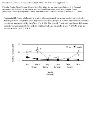
Download
1 / 22
250 likes | 461 Views
Effects of Neutron Irradiation in IG-110. Y. Katoh , M . Snead , A.A . Campbell Oak Ridge National Laboratory E. Kunimoto , M. Yamaji , T . Konishi Toyo Tanso Co ., Ltd.

E N D
Effects of Neutron Irradiation in IG-110 Y. Katoh, M. Snead, A.A. CampbellOak Ridge National Laboratory E. Kunimoto, M. Yamaji, T. KonishiToyo Tanso Co., Ltd. Presented at the 15th International Nuclear Graphite Specialist Meeting (INGSM-15), September 15-18, 2014, Hangzhou, China Disclaimer All data included in this presentation are preliminary and are subject to revision after further analysis and certification processes are complete.
Acknowledgements • Research sponsored by Toyo Tanso Co., Ltd. under contract NFE-10-02974 with UT-Battelle, LLC. • Use of HFIR sponsored by Office of Basic Energy Science, U.S. Department of Energy. • Patricia Tedder, William Comings, Stephanie Curlin, Michael McAllister, Daniel Lewis, Brian Eckhart, Chunghao Shih, Wallace Porter, Marie Williams for their work in LAMDA to obtain the presented results. NesrinCetiner and Joel McDuffee for irradiation engineering. Additional ORNL people for irradiation management, hot cell work, radiological protection, etc.
Program Summary • Temperature range significant for gas cooled reactors (300°C-1000°C) • Dose range from 7 – 40 n/m2 (x1025 [E>0.1MeV])(5 – 30 dpa) • Acquire comprehensive design properties by rabbit and target creep irradiations • Rabbit program • PIE-1 is complete – early results reported here • PIE-2 is in process • PIE-3 planned after spring 2015 • Creep program • PIE-1 in late 2014 through 2015 • PIE-2 in ~2017
Pre-Irradiation Material Properties a:Catalog value b:The measurement temperature range for the CTE is 350 to 450℃ c:The measurement temperature range for the CTE is RT to 400℃ d:3 point loading e:4 point loading
Definition of Orientations for Iso-molded Graphite Z = (~against grain) = with gravity = axial (AX) X = (~with grain) = against gravity = transverse (TR) Y = (~with grain) = against gravity = transverse (TR)
+Z(AX) -X(TR) +Y(TR) Specimen Shapes and Orientations Validation of small specimen testing in Y. Katoh et al., ASTM STP1578 (in press) 2.9=T 3=W 25=L X=Y=6 X=Y=6 Z=X=6 Z=X=6 Z=X=6 X=Y=6 Z=8 4=Z 3=Z Y=3 Y=4 Y=8 CRS (TR) TD3 (TR) TD4 (TR) CRS (AX) TD4 (AX) TD3 (AX) 2.9=T 25=L MB (AX) MB (TR) 3=W
Specimen Arrangement in Rabbits • Two capsule types • 25 capsules with 8 modulus beam specimens in each capsule • 9 capsules with a combination of compression strength and thermal diffusivity specimens
+Z(AX) -X(TR) +Y(TR) Creep Capsule Specimens X=Y=6 X=Y=6 Z=X=6 Z=X=6 Z=8 3=Z Y=3 Y=8 CRS (TR) TD3 (TR) CRS (AX) TD3 (AX) X=Y=6 Z=X=6 1.25 mm hole down center 1.25 mm hole down center Z=8 Y=8 CRP (TR) CRP (AX)
Creep Capsule Design • Loaded region has 4 CRP specimens and 1 CRS specimen in each temperature zone • Lower unloaded region has 1 CRS specimen, 2 CRP specimens, and 8 TD3 specimens in each temperature zone Upper stressed region 300°C 450°C 600°C Lower unstressed region 600°C 450°C 300°C
Data Analysis Notes • In the following plots a consistent color and plotting scheme is used: • Filled data points and solid lines are AX direction • Open data points and dotted lines are TR direction • Error bars are one standard deviation (data points without error bars are measurements from one specimen) • In plot legends the IG-110 is only listed by average temperature, which IG-430 has the material label included • Data point shapes and color family were kept the same for IG-110 and IG-430 (i.e. 319°C IG-110 red circles and IG-430 are pink circles)
Dimensional Change Burchell, HTK-7 Experiment
Volume Change Ishiyama et al. (1996)
Thermal Conductivity Ishiyama et al. (1996) 650°C
CTE of Irradiated IG-110 Mean CTE referenced to Room Temperature
CTE Changes with Neutron Fluence Mean CTE referenced to Room TemperatureCTE values at irradiation temperature
Irradiated Young’s Modulus Change Correlates with Density Change Kunimoto et al. (2009) • Irradiated Young’s modulus correlates very well with density (and electrical conductivity). Schulz (1981) Transfer efficiency factor: Field • Density exponent for irradiation-induced modulus changes appears significantly greater than that for oxidation-induced modulus decrease. a EllipsoidalPore Yoda et al. (1985) • Large (>> 1) density exponent indicates that pores responsible for modulus variations are extremely non-spherical. F 0 F = 1/3 F 1
Major Change in Structural Factor Requires Refinement of Defect Thermal Resistivity Model 1/KRD: radiation defect thermal resistivity in conventional model e: transport efficiency factor in porous medium K0: thermal conductivity of pore-free bulk 1/K0RD: intrinsic radiation defect thermal resistivity = better measure of matrix defect accumulation
Summary • PIE-1 campaign is in progress • Initial results show expected trends • All observations consistent with each other and known trends in early contraction regime • Observed difference in dimensional behavior depending on axial or transverse relation to gravity during molding • Findings / implications from additional analyses • Structural term dominates in modulus change in this dose range • Source mainly from crack closure • Decrease in intrinsic thermal conductivity more significant than in apparent conductivity • More PIE-1 and PIE-2 results to come • Higher fluence • Higher temperatures