Download
1 / 17
170 likes | 312 Views
Framing (Chap. 7). STX. Header. Packet. ETX. CRC. Frame. 1. Character-based framing (IBM Bisync, Arpanet) STX: start of text (a control character) ETX: end of text (a control character) CRC: Cyclic redundancy code (error detection only) Problems:

E N D
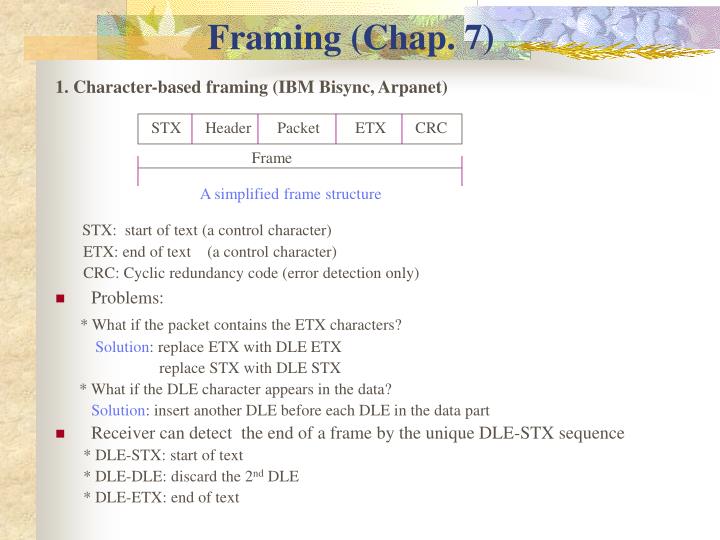
Framing (Chap. 7) STX Header Packet ETX CRC Frame 1. Character-based framing (IBM Bisync, Arpanet) STX: start of text (a control character) ETX: end of text (a control character) CRC: Cyclic redundancy code (error detection only) • Problems: * What if the packet contains the ETX characters? Solution: replace ETX with DLE ETX replace STX with DLE STX * What if the DLE character appears in the data? Solution: insert another DLE before each DLE in the data part • Receiver can detect the end of a frame by the unique DLE-STX sequence * DLE-STX: start of text * DLE-DLE: discard the 2nd DLE * DLE-ETX: end of text A simplified frame structure
Framing (cont’d) Flag Address Ctrl Packet CRC Flag Frame 2. Bit-oriented framing (HDLC) Flag: a special bit string such as DLE ETX 01111110 used in HDLC • Problems: * What if the packet consists of 01111110? Solution: use bit stuffing • Transmitter: * inserts an additional ‘0’ after every 5 consecutive ‘1’s in the frame contents. * Ex: 1 1 0 1 1 0 1 1 1 1 1 1 1 0 1 1 1 1 1 0 0 • Receiver: * removes a ‘0’ after 5 consecutive ‘1’s in the frame contents HDLC standard frame format 0 0
Framing (cont’d) 3. Length counts (byte-oriented protocol) • Transmitter: * includes a length count in the frame header • Receiver: * reads this length to determine where the frame ends • Used in DECNET (DDCMP) * DDCMP: Digital’s Data Comms. Msg. Protocol Header Data SYN SYN SOH Length … H-CRC Data D-CRC Frame for char. synchronization DDCMP frame format
Framing Errors • Problems: * What if an error occurs in the framing information such as in the flag or in the length field? • Case 1: 01111110 … 01101110 …… 01111110 …………………. 01111110 • Case 2: 01111110 … 01101110 …… 01111110 …………………. 01111110 • Solution: ask for retransmission (or re-synchronization) if errors are detected 2nd flag 1st flag Frame 1 3rd flag Frame 2 CRC 2 CRC 1 0 becomes the 2nd flag 1 becomes the 2nd flag
Ch. 8 LAN Technologies & Network Topology Most networks are local; designed for sharing Two types of communication channels: • Direct P-to-P communication • Shared communication channels Direct P-to-P Communication • Advantages * appropriate hardware can be used * connected computer can decide exactly how to send data cross the conn. * easy to enforce security & privacy • Disadvantages * # of connections is proportional to N^2, N: # of computers * cost becomes too high as N gets too large • Mainly used for long-distance communications 1 conn. 3 conn. 6 conn.
Shared Communication Channels • Networks that allow multiple computers to share a comm medium are mainly used in local area networks (LANs) • In this case, ach LAN consists of a single shared medium. The computer attached to a LAN take turns using the medium to send packets • Significance of LANs * currently the most popular form of computer networks • Locality of reference principle * A computer is more likely to communicate with computers nearby * A computer is likely to communicate with the same set of computers repeatedly
LAN Topologies • Star topology Typically, a central node (or hub) consists of an electronic device that accepts data from the sender and delivers it to the receiver • Ring topology Like star topology, the ring topology refers to logical connections among computers, not physical orientation • Bus topology All computers attached to the cable can receive signals sent by any one of them
Example Bus Network: Ethernet • History * Invented by Xerox * DEC, Intel, & Xerox later devised a production standard called DIX Ethernet * IEEE now controls Ethernet standards (similar to IEEE 802.3) • Speed * Original Ethernet: 10 Mbps * Fast Ethernet: 100 Mbps * Gigabit Ethernet: 1000 Mbps (1 Gbps) • A segment of 10 Base 5 (thick Ethernet) >= 3m <= 500 m A segment
voltage 1 0 1 0 1 1 0 0 0 1 0 1 1 • Transmission * Frames are sent using Manchester encoding * Manchester encoding uses rising and falling of edges to encode data * Ethernet uses a 64-bit preamble (1010…10) for synchronization and for signaling the beginning of a frame * IEEE 802.3 uses a 56-bit preamble (1010…10) for synchronization and plus an 8-bit of flag (10101011) to signal the beginning of a frame * The end of a frame is provided by the removal of the carrier sense signal, detected by the absence of a bit transition after the last bit of the frame check sequence 0 time
CSMA/CD Carrier Sense Multiple Access with Collision Detection • CSMA/CD * the mechanism used to coordinate transmission * allows multiple computers to access the shared medium * This is a distributed coordination; there is no central controller • Carrier sense: checking for a carrier wave * the status of the cable is determined by the electrical activity * the cable does not contain electrical signals when no computer is sending a frame * during transmission, the sender transmits electrical signals, informally called a carrier * to determine whether the cable is being used, a computer can check for a carrier • Collision detection * what happens if two or more computers find the cable idle and start sending frames simultaneously? * when the two transmitted signals reach the same point, they interfere with each other The interference is called a collision, which produces a garbled transmission
Collision detection (cont’d) * The Ethernet standard requires a sending station to monitor signals on the cable during transmission * If the signal differs from what the station is sending a collision has occurred * when a collision is detected, the sending station transmits a jamming signal, then stop transmitting immediately * Monitoring a cable during transmission is known as collision detection * To guarantee that a collision has time to reach all stations before they stop transmitting, the standard specifies 1. a maximum cable length 2. a min. frame size • Backoff * To avoid multiple collisions, the computer chooses a random delay t, t < d, d: the max. delay specified by the standard * Binary exponential backoff: doubling the range of the random delay after each collision 1st collison: wait for t, 0 < d 2nd collision: ,, , 0 < 2d 3rd collision: ,, , 0 < 4d …
Wireless LANs & CSMA/CA d d C1 C2 C3 • Limited range * wireless LANs transmitters use low power short transmission distance * wireless units located far apart or behind obstructions will not receive each other’s transmission * lack of full communication CSMA/CD will not work • Example in the diagram * max. transmission distance: d * C1 and C3 do not receive each other’s transmission * when C1 C2, C3 won’t be able to sense the carrier & may proceed to send, causing a collison * if C1 C2 and C3 C2 at the same time, only C2 can detect the collision d: the maximum transmission distance
d d Wireless LANs & CSMA/CA C1 C2 C3 * to ensure the units share the transmission media correctly use a modified scheme known as CSMA/CA • How it works * both side send small control message first followed by data transmission * C1 C2 with a control message (C3 does not know this transmission) C2 C1 with another control msg (C3 knows something is going on now) C1 starts sending data frames to C2 • Purpose * to inform all units in the range of C1 or C2 before transmission of data to avoid collision during the transmission of data frames * Note that collision may still occur during the transmission of control messages apply random backoff before resending the control message
Example Ring Network: IBM Token Ring (16 Mbps) Computer not holding the token passes bits Sender transmits bits of a frame • Conceptual flow of bits during transmission • Token Ring * Token: a special bit pattern of 3 bytes long, different from a normal data frame * A token ring network operates as a single, shared medium * When there is no traffic on the ring, the token circulates endlessly, waiting for a station to seize it • Procedure (when a computer has data to send) * waits for a free token to arrive (permission to send) * sets the token bit from 0 to 1, transmits one frame, regenerate the 3-byte token * puts the token out onto the ring (to the next computer) Receiver passes bits and makes a copy Sender receives bits of the frame bit stuffing may be used
Another Example Ring Network: FDDI • FDDI (Fiber Distributed Data Interconnect) * 100 Mbps, use optical fiber to connect computers * A FDDI network consists of two complete rings; one is used to send data when everything is working fine The other is used only when the 1st ring fails • Self healing * the process of automatic reconfiguration to avoid a failure * FDDI is known as a self healing netwrok failed station loop back loop back outer ring: for data inner ring: for backup
Example Star Network: ATM • Basic element of ATM (Asynchronous Transfer Mode) * an electric switch (ATM switch) * one or more interconnected ATM switches form a central hub to which all computers (or LANs) attach * An example: a switch 6 computers attached (a workgroup ATM) • Speed * 155 Mbps (the primary rate) or faster • Switching * A switch does not propagate data to any computers except the pair that communicate high performance computer ATM Switch a connection (each connection uses a pair of fibers)
Example Star Network: ATM ATM switch (need to perform speed & protocol conversion) • Example of a Backbone ATM LAN Note:implies the use of ATM as a data transport protocol somewhere within the local premises FDDI 100 link to other ATM network + + + + + + 622 Mbps + + + + + + 155 155 link to public ATM network 155 10-Mbps Ethernet + + + + + + + + + + + + 100-Mbps Ethernet