Download
1 / 51
510 likes | 706 Views
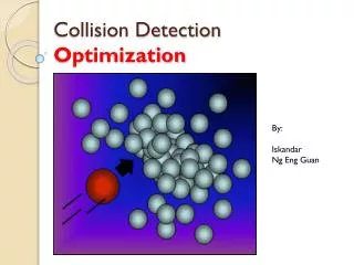
Collision Detection. CSE169: Computer Animation Instructor: Steve Rotenberg UCSD, Winter 2005. Collisions. Collision Detection Collision detection is a geometric problem

E N D
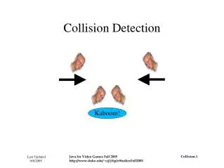
Collision Detection CSE169: Computer Animation Instructor: Steve Rotenberg UCSD, Winter 2005
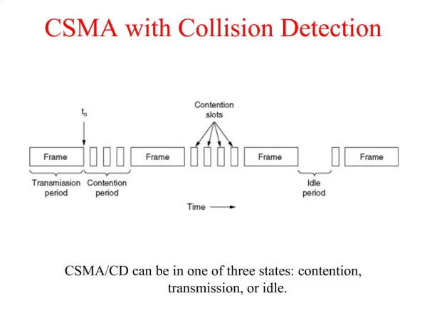
Collisions • Collision Detection • Collision detection is a geometric problem • Given two moving objects defined in an initial and final configuration, determine if they intersected at some point between the two states • Collision Response • The response to collisions is the actual physics problem of determining the unknown forces (or impulses) of the collision
Collision Detection • ‘Collision detection’ is really a geometric intersection detection problem • Main subjects • Intersection testing (triangles, spheres, lines…) • Optimization structures (octree, BSP…) • Pair reduction (reducing N2 object pair testing)
Intersection Testing • General goals: given two objects with current and previous orientations specified, determine if, where, and when the two objects intersect • Alternative: given two objects with only current orientations, determine if they intersect • Sometimes, we need to find all intersections. Other times, we just want the first one. Sometimes, we just need to know if the two objects intersect and don’t need the actual intersection data.
Primitives • We often deal with various different ‘primitives’ that we describe our geometry with. Objects are constructed from these primitives • Examples • Triangles • Spheres • Cylinders • AABB = axis aligned bounding box • OBB = oriented bounding box • At the heart of the intersection testing are various primitive-primitive tests
Particle Collisions • For today, we will mainly be concerned with the problem of testing if particles collide with solid objects • A particle can be treated as a line segment from it’s previous position to it’s current position • If we are colliding against static objects, then we just need to test if the line segment intersects the object • Colliding against moving objects requires some additional modifications that we will also look at
Basic Components class Segment { Vector3 A,B; }; class Intersection { Vector3 Position; Vector3 Normal; Material *Mtl; (Mtl can contain info about elasticity, friction, etc) };
Primitives class Primitive { virtual bool TestSegment(const Segment &s, Intersection &i); }; class Sphere:public Primitive… class Triangle:public Primitive… class Cylinder:public Primitive…
Segment vs. Triangle • Does segment ab intersect triangle v0v1v2 ? •
Segment vs. Triangle • First, compute signed distances of a and b to plane • Reject if both are above or both are below triangle • Otherwise, find intersection point x •
Segment vs. Triangle • Is point x inside the triangle? (x-v0)·((v2-v0)×n) > 0 • Test all 3 edges v2 v2-v0 x-v0 x • v0 v1 (v2-v0)×n
Faster Way • Reduce to 2D: remove smallest dimension • Compute barycentric coordinates x' =x-v0 e1=v1-v0 e2=v2-v0 α=(x'×e2)/(e1×e2) β=(x'×e1)/(e1×e2) • Reject if α<0, β<0 or α+β >1 v2 β x v0 α v1
Segment vs. Mesh • To test a line segment against a mesh of triangles, simply test the segment against each triangle • Sometimes, we are interested in only the ‘first’ hit along the segment from a to b. Other times, we want all intersections. Still other times, we just need any intersection. • Testing against lots of triangles in a large mesh can be time consuming. We will look at ways to optimize this later
Segment vs. Moving Mesh • M0 is the object’s matrix at time t0 • M1 is the matrix at time t1 • Compute delta matrix: M1=M0·MΔ MΔ=M0-1·M1 • Transform a by MΔ a'=a·MΔ • Test segment a'b against object with matrix M1
Triangle vs. Triangle • Given two triangles: T1 (u0u1u2) and T2 (v0v1v2) v2 u2 v0 T2 T1 u0 v1 u1
Triangle vs. Triangle Step 1: Compute plane equations n2=(v1-v0)×(v2-v0) d2=-n2·v0 v2 v2-v0 n v1 v1-v0 v0
Triangle vs. Triangle • Step 2: Compute signed distances of T1 vertices to plane of T2: di=n2·ui+d2 (i=0,1,2) • Reject if all di<0 or all di>0 • Repeat for vertices of T2 against plane of T1 u0 d0
Triangle vs. Triangle • Step 3: Find intersection points • Step 4: Determine if segment pq is inside triangle or intersects triangle edge q p
Mesh vs. Mesh • Geometry: points, edges, faces • Collisions: p2p, p2e, p2f, e2e, e2f, f2f • Relevant ones: p2f, e2e (point to face & edge to edge) • Multiple simultaneous collisions
Moving Mesh vs. Moving Mesh • Two options: ‘point sample’ and ‘extrusion’ • Point sample: • If objects intersect at final positions, do a binary search backwards to find the time when they first hit and compute the intersection • This approach can tend to miss thin objects • Extrusion: • Test ‘4-dimensional’ extrusions of objects • In practice, this can be done using only 3D math
Moving Meshes: Extrusion • Use ‘delta matrix’ trick to simplify problem so that one mesh is moving and one is static • Test moving vertices against static faces (and the opposite, using the other delta matrix) • Test moving edges against static edges (moving edges form a quad (two triangles))
Intersection Issues • Performance • Memory • Accuracy • Floating point precision
Impact vs. Contact • In physics simulation, there is usually a distinction between impacts and contacts • Impacts are instantaneous collisions between objects where an impulse must be generated to prevent the velocities at the impact location from allowing the objects to interpenetrate • Contacts are persistent and exist over some range of time. In a contact situation, the closing velocities at the contact location should already be 0, so forces are needed to keep the objects from accelerating into each other. With rigid bodies, contacts can include fairly complex situations like stacking, rolling, and sliding
Impact vs. Contact • Neither impact nor contact is particularly easy to handle correctly • In the case of particles, it’s not so bad, but with rigid bodies, it can be tough • As we are mainly just concerned with the physics of particles, we will not worry about the more complex issues for now • Also, we will just focus on handling impacts, as they are generally needed first. Continuous contact will just be handled by allowing particles to impact frame after frame
Impacts • When two solid objects collide (such as a particle hitting a solid surface), forces are generated at the impact location that prevent the objects from interpenetrating • These forces act over a very small time and as far as the simulation is concerned, it’s easiest to treat it as an instantaneous event • Therefore, instead of the impact applying a force, we must use an impulse
Impulse • An impulse can be thought of as the integral of a force over some time range, which results in a finite change in momentum: • An impulse behaves a lot like a force, except instead of affecting an object’s acceleration, it directly affects the velocity • Impulses also obey Newton’s Third Law, and so objects can exchange equal and opposite impulses • Also, like forces, we can compute a total impulse as the sum of several individual impulses
Compression & Restitution • The collision can be thought of as having two phases: compression & restitution • In the compression phase, the energy of the two objects is changed from kinetic energy of motion into deformation energy in the solids • If the collision is perfectly inelastic (e=0), then all of the energy is lost and there will be no relative motion along the collision normal after the collision • If the collision is perfectly elastic (e=1), then all of the deformation energy will be turned back into kinetic energy in the restitution phase and the velocity along the normal will be the opposite of what it was before the collision
Collisions • Consider the case of a particle colliding with a heavy object. The object is moving with velocity vobj • The particle has a velocity of v before the collision and collides with the surface with a unit normal n • We want to find the collision impulse j applied to the particle during the collision
Collisions • We take the difference between the two velocities and dot that with the normal to find the closing velocity •
Collisions • Let’s first consider a collision with no friction • The collision impulse will be perpendicular to the collision plane (i.e., along the normal) and will be large enough to stop the particle (at least)
Friction • The Coulomb friction model says:
Friction • As we are not considering static contact, we will just use a single dynamic friction equation • For an impact, we can just compute the impulse in the exact same way as we would for dynamic friction • We can use the magnitude of the elasticity impulse as the normal impulse
Collision Handling • For particles and cloth, the following approach works effectively: 1. Compute forces (springs, aero…) 2. Integrate motion (Euler step) 3. Test if particles hit anything 3.1 Compute & apply impulse (adjust velocity) 3.2 Adjust position
Position Adjustment • Moving the particle to a legal position isn’t always easy • There are different possibilities: • Move it to a position just before the collision • Put it at the collision point • Put it at the collision point plus some offset along the normal • Compute where it would have gone if it bounced • Computing the bounced position is really the best, but may involve more computation and in order to do it right, it may require further collision testing…
Position Adjustment • • • • • •
Bouncing • Computing the bounced position is the best approach, as it is consistent with the rest of the physics model • We need to determine when exactly the collision happened (we can just assume that the particle traveled at a constant velocity within the frame) • We then compute the impulse and adjust the velocity • Then, we move the particle forward by the amount of time remaining within the frame • Ideally, we should then check collisions on this new path • A particle getting stuck in a narrow crack might bounce several times, so we should put a cap on the maximum number of bounces allowed, then just stop the particle at some point if it exceeds the limit
Optimization Structures • BV, BVH (bounding volume hierarchies) • Octree • KD tree • BSP (binary separating planes) • OBB tree (oriented bounding boxes- a popular form of BVH) • K-dop tree • Uniform grid • Hashing • Dimension reduction
Testing BVH’s TestBVH(A,B) { if(not overlap(ABV, BBV) return FALSE; else if(isLeaf(A)) { if(isLeaf(B)) { for each triangle pair (Ta,Tb) if(overlap(Ta,Tb)) AddIntersectionToList(); } else { for each child Cb of B TestBVH(A,Cb); } } else { for each child Ca of A TestBVH(Ca,B) } }
Optimization Structures • All of these optimization structures can be used in either 2D or 3D • Packing in memory may affect caching and performance