Download

1 / 10
100 likes | 236 Views
Proton Source Improvement Workshop Cogging. W. Pellico Dec 6&7 2010. Booster Gap Three consecutive high intensity pulses (un-notched) will exceed extraction loss limit! . Booster creates a 3 gap notch The gap is created using two pulsed kickers Notcher – High Voltage Kicker at Long 5

E N D
Proton Source Improvement WorkshopCogging W. Pellico Dec 6&7 2010
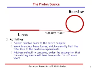
Booster Gap Three consecutive high intensity pulses (un-notched) will exceed extraction loss limit! • Booster creates a 3 gap notch • The gap is created using two pulsed kickers • Notcher – High Voltage Kicker at Long 5 • Nocker - Lower Voltage Kicker at Long 12 • Used to clean out Notched Beam • Required for Cogged Cycles • Beam is kicked into collimator region and Long 13 • The gap trigger is created and synched by modules in Booster Low Level room (several modules required) • Synchronization of gap can be done to Pre-Acc notching • Notch for non-cogged cycles occurs at 400 Mev • Cogged notch occurs at ~700 MeV
Uncogged Cycle – Notch Crated at Injection Gap Creation Scope Trace – Three Bucket Notch Cogged Cycle – Notch Created Later
Cogging Motivation • Booster needs to fire (5) kickers in a (3 bucket) gap to keep losses down at extraction • Booster syncs the gap to a MI marker (‘OAA’) • Booster will extract on OAA +/- 1 bucket MI with circulating beam MI = 7*84 Bunches 3319 Meters
Cogging History • Around 1998 – the first cogging studies (Webber, Pellico) • 2002: VXI board layout completed based upon early studies • 2005: Added additional automatic Update Trip Plan • 2006: Added BES over-ride • Multibatch MI operations • High Intensity Cycles & Rates • Slip Stacking for Pbar Production • Slip Stacking for Numi • MI cycles used for Tevatron loading • Cogged but not Notched
Wait for Booster To MI Event ($14 $19..) Was this the first event of load cycle Yes No Make a ‘Trip Plan’ Start Cogging Process End of cycle: Get ready for next
Current Typical Timeline $14 $19 $19 $19 $19 $14 $19 $19 $19 $19 $1D $1D $1D First Cycle For Trip Plan
Typical Plots Showing Cogging Rpos Variations for several MI Cycles Typically - Horizontal position will vary +/- 6mm (Depends upon gain setting ) There are two types of correction: Fixed and Proportional
Slippage of Gap vs ‘Trip Plan’ • Slippage in a cycle varies by > 200 buckets • About 3 circumferences • Notch is essentially at a random position w.r.t the beam circulating in the Main Injector Gap Position tracking Relative to Trip Plan Gap ~ 3 turns Robert Zwaska Booster Cogging
Conclusion/Issues • Dynamic Aperture • Beam Emittances • Beam Losses • Higher losses on Cogged Cycles • Notch at Higher Energy • Gap not as clean • Orbit Control/Scraping • Lots of hardware to maintain • Jitter – Extraction and Gap Kickers • Ready for Upgrade • It works – much better then I would ever have hopped….