Download
1 / 1
20 likes | 423 Views
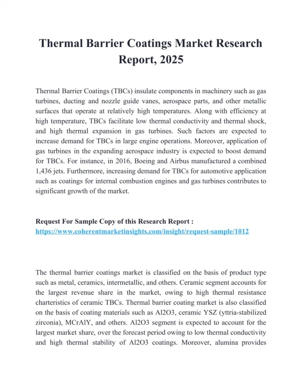
Modelling of self-healing thermal barrier coatings. PhD Candidate: Sathiskumar A Ponnusami Department : ASM Section: ASCM Supervisor: Dr. Sergio Turteltaub Start date: 1-10-2011 Funding: IOP Self healing materials Cooperations : NLR, KLM, Sulzer Turboservices. Approach

E N D
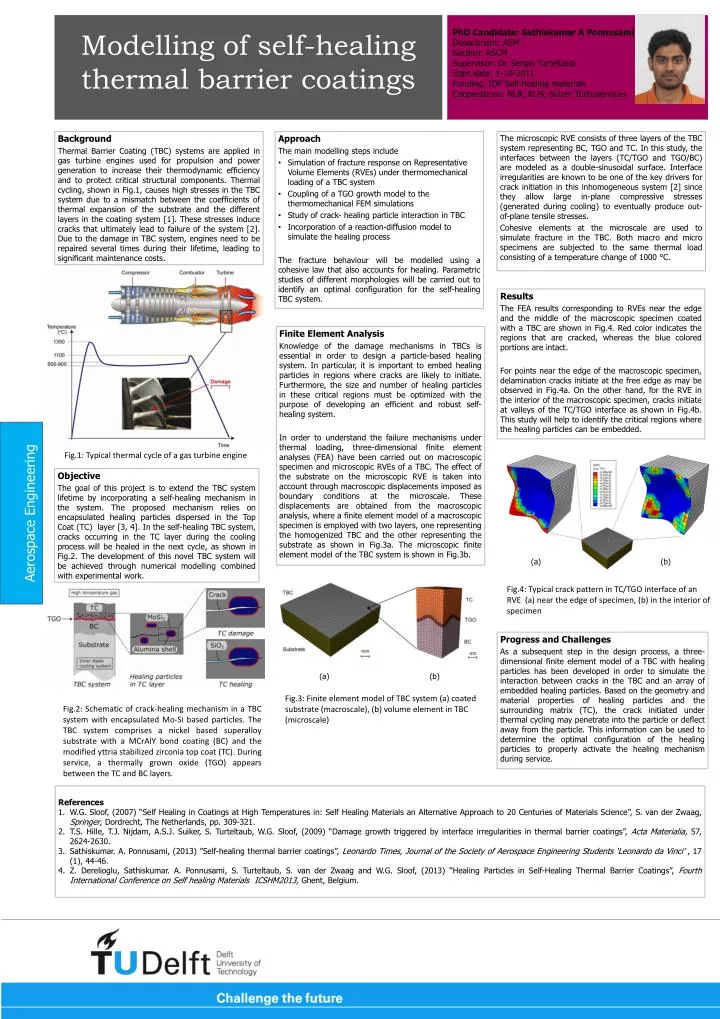
Modelling of self-healing thermal barrier coatings PhD Candidate: Sathiskumar A Ponnusami Department: ASM Section: ASCM Supervisor: Dr. Sergio Turteltaub Start date: 1-10-2011 Funding: IOP Self healing materials Cooperations: NLR, KLM, SulzerTurboservices Approach The main modelling steps include Simulation of fractureresponse on Representative Volume Elements (RVEs) underthermomechanicalloading of a TBC system Coupling of a TGO growth model to the thermomechanicalFEM simulations Study of crack- healing particle interaction in TBC Incorporation of a reaction-diffusion model to simulatethe healingprocess The fracture behaviour will be modelled using a cohesive law that also accounts for healing. Parametric studies of different morphologies will be carried out to identify an optimal configuration for the self-healing TBC system. • Background • Thermal Barrier Coating (TBC) systems are applied in gas turbine engines used for propulsion and power generation to increase their thermodynamic efficiency and to protect critical structural components. Thermal cycling, shown in Fig.1, causes high stresses in the TBC system due to a mismatch between the coefficients of thermal expansion of the substrate and the different layers in the coating system [1]. These stresses induce cracks that ultimately lead to failure of the system [2]. Due to the damage in TBC system, engines need to be repaired several times during their lifetime, leading to significant maintenance costs. • The microscopic RVE consists of three layers of the TBC system representing BC, TGO and TC. In this study, the interfaces between the layers (TC/TGO and TGO/BC) are modeled as a double-sinusoidal surface. Interface irregularities are known to be one of the key drivers for crack initiation in this inhomogeneous system [2] since they allow large in-plane compressive stresses (generated during cooling) to eventually produce out-of-plane tensile stresses. • Cohesive elements at the microscale are used to simulate fracture in the TBC. Both macro and micro specimens are subjected to the same thermal load consisting of a temperature change of 1000 °C. Results The FEA results corresponding to RVEs near the edge and the middle of the macroscopic specimen coated with a TBC are shown in Fig.4. Red color indicates the regions that are cracked, whereas the blue colored portions are intact. For points near the edge of the macroscopic specimen, delamination cracks initiate at the free edge as may be observed in Fig.4a. On the other hand, for the RVE in the interior of the macroscopic specimen, cracks initiate at valleys of the TC/TGO interface as shown in Fig.4b. This study will help to identify the critical regions where the healing particles can be embedded. Finite Element Analysis Knowledge of the damage mechanisms in TBCs is essential in order to design a particle-based healing system. In particular, it is important to embed healing particles in regions where cracks are likely to initiate. Furthermore, the size and number of healing particles in these critical regions must be optimized with the purpose of developing an efficient and robust self-healing system. In order to understand the failure mechanisms under thermal loading, three-dimensional finite element analyses (FEA) have been carried out on macroscopic specimen and microscopic RVEs of a TBC. The effect of the substrate on the microscopic RVE is taken into account through macroscopic displacements imposed as boundary conditions at the microscale. These displacements are obtained from the macroscopic analysis, where a finite element model of a macroscopic specimen is employed with two layers, one representing the homogenized TBC and the other representing the substrate as shown in Fig.3a. The microscopic finite element model of the TBC system is shown in Fig.3b. Aerospace Engineering Fig.1: Typical thermal cycle of a gas turbine engine Objective The goal of this project is to extend the TBC system lifetime by incorporating a self-healing mechanism in the system. The proposed mechanism relies on encapsulated healing particles dispersed in the Top Coat (TC) layer [3, 4]. In the self-healing TBC system, cracks occurring in the TC layer during the cooling process will be healed in the next cycle, as shown in Fig.2. The development of this novel TBC system will be achieved through numerical modelling combined with experimental work. (a) (b) Fig.4: Typical crack pattern in TC/TGO interface of an RVE (a) near the edge of specimen, (b) in the interior of specimen Progress and Challenges As a subsequent step in the design process, a three-dimensional finite element model of a TBC with healing particles has been developed in order to simulate the interaction between cracks in the TBC and an array of embedded healing particles. Based on the geometry and material properties of healing particles and the surrounding matrix (TC), the crack initiated under thermal cycling may penetrate into the particle or deflect away from the particle. This information can be used to determine the optimal configuration of the healing particles to properly activate the healing mechanism during service. (a) (b) Fig.3: Finite element model of TBC system (a) coated substrate (macroscale), (b) volume element in TBC (microscale) Fig.2: Schematic of crack-healing mechanism in a TBC system with encapsulated Mo-Si based particles. The TBC system comprises a nickel based superalloy substrate with a MCrAlY bond coating (BC) and the modified yttria stabilized zirconia top coat (TC). During service, a thermally grown oxide (TGO) appears between the TC and BC layers. References W.G. Sloof, (2007) “Self Healing in Coatings at High Temperatures in: Self Healing Materials an Alternative Approach to 20 Centuries of Materials Science”, S. van der Zwaag, Springer, Dordrecht, The Netherlands, pp. 309-321. T.S. Hille, T.J. Nijdam, A.S.J. Suiker, S. Turteltaub, W.G. Sloof, (2009) “Damage growth triggered by interface irregularities in thermal barrier coatings”, ActaMaterialia, 57, 2624-2630. Sathiskumar. A. Ponnusami, (2013) ”Self-healing thermal barrier coatings”, Leonardo Times, Journal of the Society of Aerospace Engineering Students ‘Leonardo da Vinci’ , 17 (1), 44-46. Z. Derelioglu, Sathiskumar. A. Ponnusami, S. Turteltaub, S. van der Zwaag and W.G. Sloof, (2013) “Healing Particles in Self-Healing Thermal Barrier Coatings”, Fourth International Conference on Self healing Materials ICSHM2013, Ghent, Belgium.