Download

1 / 35
350 likes | 501 Views
Lecture 1 Design Hierarchy. Chapter 1. Digital System Design Flow. Register-Transfer Levl (RTL) e.g. VHDL/Verilog Gate Level Design Circuit Level Design Physical Layout. Verilog. Include a set of 26 predefined functional models of common combinational logic gates called primitives .

E N D
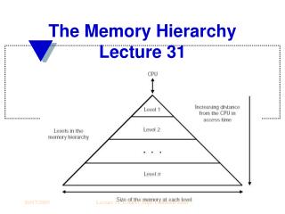
Lecture 1Design Hierarchy Chapter 1
Digital System Design Flow • Register-Transfer Levl (RTL) • e.g. VHDL/Verilog • Gate Level Design • Circuit Level Design • Physical Layout
Verilog • Include a set of 26 predefined functional models of common combinational logic gates called primitives. • Primitives • The most basic functional objects that can be used to compose a design • Are built into the language by means of internal truth tables • Examples: and, nand, or, nor, xor, xnor
More on Primitives • 3-input nand primitive • Input signal a, b, and c • Output signal y • Each primitive has ports (corresponding to hardware pins and terminals) • The output port(s) of a primitive must be first in the list, followed by the primitive’s input ports.
Instantiated Primitives • Instantiated Primitives (nor, and,nand) are connected by wires. • A wire is a data-type which is used to establish connectivity in a design, just as a physical wire establishes connectivity between gates.
Example: a Full Adder • Binary Addition • Gate-Level Synthesis • Verilog Representation
Derivation of ∑ • Question: What primitive best implements ∑? • Inputs: A, B • Outputs: xor (∑, A, B)
Derivation of Carry Out • Question: What primitive best implements Co? • Inputs: A, B • Outputs: and (Co, A, B)
A Half Adder A half adder is useful for adding LSB.
Limitation of a Half Adder A half-adder does not account for carry-in.
Truth Table of ∑ of a Full Adder Identical to ∑ of a Half Adder Cin+B+A=Cin+∑HA=Cin XOR ∑HA
Truth Table of Co of a Full Adder Identical to ∑ of a Half Adder Use a Half Adder with Cin and ∑HA to generate Co
Explanation • The keywords module and endmoduleencapsulate the text that describes the module • The module name is Add_full • Module Ports are • Input a, b, c_in • Output c_out, sum • Module instances: Add_half, or
Nested Module • Add_half is a child module of Add_full
Gate Level Design • Basic Gates • AND, NAND,OR, NOR, XOR, XNOR,NOT • Universal Gates • NAND Gates • NOR Gates • Multiple Inputs Logic Gates
Physical Design • Floor Planning • Estimates of the area of major units in the chip and defines their relative placements. • Estimate wire lengths and wring congestions. • Challenge: estimate the size of each unit without proceeding through a detailed design of the chip. • Layout • Design Verification • Tapeout
A Sample Floor Plan λ= ½ of minimum channel length
Layout of an Inverter In a 0.6 um process 4/2=1.2 um/0.6 um.
Design Verification • LVS (Layout vs. Schematic) checks that transistors in a layout are connected in the same way as in the circuit schematic. • DRC (Design Rule Checkers) verify that the layout satisfies design rules. • ERC (Electrical Rule Checkers) scan for problems such as noise or premature wearout.
Tapeout • Tapeoutgets its name from the old practice of writing a specifications of masks to a magnetic tape. • GDS • Foundries: • TSMC • UMC • IBM
1 • Red: Top layer trace • Green: Via • Blue: Bottom layer trace 7 Low Cost Package 12