Download
1 / 28
280 likes | 327 Views
Explore the evolution of computer networks, the OSI model, data link layer tasks, flow control mechanisms, and routing algorithms. Learn about network topologies, medium access control, packet-switched networks, and more.

E N D
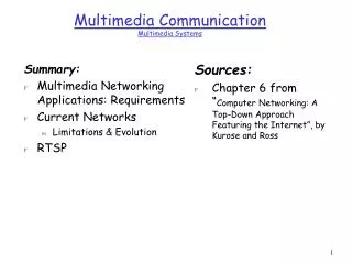
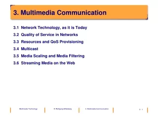
3. Multimedia Communication • 3.1 Network Technology, as it is Today • 3.2 Quality of Service in Networks • 3.3 Resources and QoS Provisioning • 3.4 Multicast • 3.5 Media Scaling and Media Filtering • 3.6 Streaming Media on the Web
3.1 Network Technology, as it is Today • The computer networks we have today were designed with data commu-nication in mind, for discrete pieces of data only. We will now look at the mechanisms in existing networks and see why the communication algo-rithms and protocols that were designed for discrete media are inappro-priate for continuous media.
Protocol Architecture in Layers • All network protocol architectures we have today are based on the concept of layers.
Layer application protocol 7 7 presentation protocol 6 6 session protocol 5 5 transport protocol 4 4 intermediate system (router) 3 2 1 Host B Host A The ISO Reference Model for Open System Interconnection (OSI)
receiver data AH data PH data SH data TH data NH data DH data DT bits Packet Headers • Typically, each layer adds a header, leading to a packet structure as shown below. Layer 2 also adds a trailer. sender physical link
Point-to-Point vs. Broadcast Networks • Point-to-Point Network • Pairs of stations are connected by a physical link. The network has the topology of a graph of nodes and edges. • Each message flows into one direction. Acknowledgements must be sent explicitly. • Broadcast requires explicit replication of the message. • Broadcast Network • Several stations share the physical medium. • All stations hear all messages. • If two stations send at the same time, the message is destroyed. • The sender can hear his own message. If the sender hears exactly what he has • sent, he can assume that all receivers have also heard the message • (implicit acknowledgement).
Medium Access Control (MAC) • Problem • Broadcast medium • Independent stations • => there will be send collisions. • Solution • Medium access control • Two principles for MAC: • Collision detectionLet the collision happen, detect it, repeat the transmission. • Collision avoidanceUse a circulation token to explicitly control the access right to the medium.
CSMA/CD • CSMA/CD = Carrier Sense Multiple Access with Collision Detection • Standardized as ISO IS 8802/3: MAC and physical layer for CSMA/CD • Topology: bus
CSMA/CD: Protocol (1) Multiple access
CSMA/CD: Protocol (2) Collision!
The Data Link Layer (Layer 2) • Tasks of the Data Link Layer (Layer 2) • Conceal bit errors (errors on the transmission line) between neighboring nodes • Provide flow control between neighboring nodes • In LANs also: Implement the MAC protocol
S R B l o c k ( 0 ) B l o c k ( 1 ) B l o c k ( 2 ) B l o c k ( 3 ) B l o c k ( 4 ) B l o c k ( 5 ) B l o c k ( 2 ) B l o c k ( 3 ) B l o c k ( 4 ) B l o c k ( 5 ) Sequence Numbers • Sequence numbers are used to uniquely identify data packets. The are used by the receiver to acknowledge specific packets. One acknowledgement (ACK) can acknow-ledge multiple data packets. 0 1 2 ) 1 ( k c A 3 4 g 5 n discard i s s 2 s discard t u e c o 3 o e discard r p m i 4 t ) 3 ( k c 5 A ) 4 ( k c A ) 5 ( k c A
Retransmission in "Go-back-n“ mode • In case of a bit transmission error no ACK will be sent. When the sender‘s timer ex-pires he will retransmit the missing packet and all packets sent later.
sender valve axis nail receiver Principle of Flow Control • The flow control mechanism prevents a sender from overflowing a (slower) recei-ver.
Sliding Window Flow Control • After connection setup the sender has the right to send as many packets as the • window size indicates. • After that he must wait until he receives an ACK from the receiver. One ACK can • confirm several packets. • The receiver can send ACKs before the window is fully used up. The ACK policy is • not standardized. • Example: window size = 3
Packet-Switched Networks • Intermediate systems contain only the layers 1-3. An example are Internet routers.
Virtual Circuits vs. Datagrams • Virtual Circuit • The path through the network is established at connection setup time. It remains the same for all packets for the duration of the entire connection. The intermediate nodes store path status information. • Datagrams • The destination address in each packet determines the next hop on the path. For each datagram the next hop is determined separately in each intermediate node. Different packets can take different paths, e.g., when a link has gone down.
Routing (1) • Each node contains a routing table with next-hop information for each destination address. • Network topology for our examples
Routing (2) Packet forwarding based on the routing table
Routing Algorithms • Task of the routing algorithm • Determine the best path for packets from a given source node to a given destin-ation node • Load the routing tables in all nodes such that all best paths are known
Idea 1: Every Node Knows the Full Topology • Use Dijkstra‘s algorithm for SHORTEST PATHS • Build a tree of shortest paths from the sender (root) to all receivers as follows: • Begin with the root • Repeat until all nodes have been reached: • Of all those nodes not yet in the tree, add the one which is a neighbor of a tree node and has the shortest path from the root. • A more detailed description of this algorithm can be found in any book on algorithms, e.g.: R. Rivest, Ch. Leiserson, Th. Cormen: Introduction To Algorithms, McGraw Hill, 1990 • Problems • How do all nodes learn the current topology of the entire network? How can incon-sistencies in a transition period be avoided when some nodes have already received the new topology, some still the old one (routing loops)?
bc ab cd de ad Example for OSPF (open shortest path first) Routing • (a) network in stable condition B C ce E D A (b) links bc and ad failed (c) after an exchange of OSPF messages
Idea 2: Routing with Distance Vectors • Only the distance to the destination and the next hop to take is known locally. • Distance vectors are exchanged periodically with neighbor nodes in routing table update messages. (a) E is added as a new node
Distance Vector Routing (b) after an additional round of messages The protocol RIP (Routing Information Protocol) of the Internet is an example of distance vector routing.
Internet Addresses • An IP address is a hierarchical 32-bit address with a netid and a hostid. This keeps routing tables small and allows decentralized assignment of host addresses.For point-to-point addressing three classes of addresses are provided: For reasons hard to understand, a notation with four decimal numbers (one for each byte) is popular. Example 192.5.48.0 for a small LAN (class C)
Consequences for Multimedia Communication • The traditional algorithms and protocols destroy the continuous flow of packets! They create considerable jitter (variance in the delay). This is true for • all MAC protocols in LANs • error control by retransmission (e.g., Go-Back-n) • flow control by sliding window (typically leads to stop-and-go traffic) • and many more algorithms! • The traditional algorithms and protocols provide no QoS guarantees!Traditional networks, in particular the Internet, are thus often called „best effort networks“. • The traditional algorithms and protocols provide no support for multicast!