Download
1 / 57
600 likes | 772 Views
Introduction to Data Communication and Computer Networks. 2 nd semester 2018 - 2019. 205NET LOC. -Introduction to Communication Systems , Networks architecture, and OSI Reference Model. Outline. What is Data Communication Communication System Model.

E N D
Introduction to Data Communication and Computer Networks 2nd semester 2018 - 2019
205NET LOC • -Introduction to Communication Systems , Networks architecture, and OSI Reference Model.
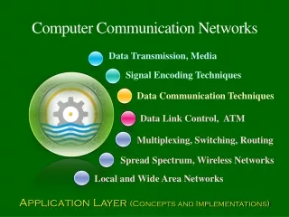
Outline • What is Data Communication • Communication System Model • Network definition, elements, purposes. • Different Network Classifications • The Functions of the LAYERS IN THE OSI MODEL
What is Data Communication • Communication Sharing of Information. • Local Sharing: face to face • Remote Sharing: over some distance. • Data information being shared, e.g. text, numbers, images, audio, video. • Data Communications: exchange of data between two (or more) devices via some transmission medium.
Communication Communication System
Communication System Model • A communication system is combination of hardware (physical equipment) and software (programs) that transfer information from source to destination
Transmitter Source Destination Receiver Transmission system
Example: Computer to Computer • Transmitter (Tx) is built into source computer (Network Interface Card) • Receiver (Rx) is built into destination computer • Transmission system is single link between two computers
Example: Old Dialup Connection • Source and transmitter are separate devices (similar at destination). • Transmission system is telephone network.
Example: Communications via the Internet • Source and transmitter may support different Technologies • Transmission system is the Internet
General Model for Communications via a Network • Source system generates data • Intermediate systems receive signal from previous system and then transmit to next system • Destination system receives and processes the data • Source and destination are connected via multiple transmission systems (or links) to form a network
Challenges with Link Communications • How to convert information into transmittable signals? • What are the characteristics of signals? • What transmission media to use? • How to know who is at other end? • How to deal with errors? • How to share media amongst two or more transmitters?
Challenges with Networked Communications • How do intermediate systems receive/send data? • How to select which intermediate systems to send via? • What happens if failures within intermediate systems? • How to create applications without knowing the details of underlying network and technologies?
What is a Network? • A computer network, often simply referred to as a network, is
Elements of Network • Hardware equipment. • Network OS/ software. • Communication channel / Transmission media. • Information / data / resource. • Protocol.
Network Classification • We can classify networks in different ways:
Local Area Network (LAN) • A network that connects a relatively small number of machines in a relatively close geographical area. Wide Area Network (WAN) • A network that connects two or more local-area networks over a potentially large geographic distance
Clients and Servers • In a client/server network arrangement, network services are located in a dedicated computer whose only function is to respond to the requests of clients.
Network Clients (Workstation) • Computers that request network resources or services Network Servers • Computers that manage and provide network resources and services to clients • Usually have more processing power, memory and hard disk space than clients • Run Network Operating System that can manage not only data, but also users, groups, security, and applications on the network • Servers often have a more stringent requirement on its performance and reliability
Peer-to-Peer Networks • Peer-to-peer network is also called workgroup • No hierarchy among computers all are equal • No administrator responsible for the network
Where peer-to-peer network is appropriate: • 10 or less users • No specialized services required • Security is not an issue • Only limited growth in the foreseeable future
Hub Network Topology A topology is a way of “laying out” the network. Topologies can be either physical or logical. • 3 basic types Ring Topology Bus Topology • Star Topology
Star Topology • Each computer has a cable connected to a single point • More cabling, hence higher cost • All signals transmission through the hub; if down, entire network down • Depending on the intelligence of hub, two or more computers may send message at the same time Bus Topology • Simple and low-cost • A single cable called a trunk (backbone, segment) • Only one computer can send messages at a time • Passive topology - computer only listen for, not regenerate data
Ring Topology • Every computer serves as a repeater to boost signals • Typical way to send data: • Token passing: only the computer who gets the token can send data • Disadvantages • Difficult to add computers • More expensive • If one computer fails, whole network fails
Layers In The OSI Model • In this section we briefly describe the functions of each layer in the OSI model. • Topics discussed in this section: • Physical Layer • Data Link Layer • Network Layer • Transport Layer • Session Layer • Presentation Layer • Application Layer
The Application Layer • The application layer enable the user to access the network. • These applications produce the data, which has to be transferred over the network. • This layer also serves as window for the application services to access the network and for displaying the received information to the user.
The Presentation Layer • The presentation layer is responsible for translation, compression, and encryption.
The Session Layer • This layer is responsible for establishment of connection, maintenance of sessions, authentication and also ensures security.
The Session Layer ‘s Functions The functions of the session layer are : • Session establishment, maintenance and termination: The layer allows the two processes to establish, use and terminate a connection. • Dialog Controller : The session layer determines which device will communicate first and the amount of data that will be sent. • Synchronization : This layer allows a process to add checkpoints which are considered as synchronization points into the data.
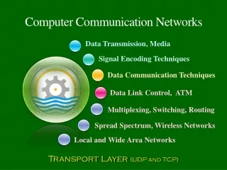
The Transport Layer • Transport layer is responsible for process-to-process delivery of the entire message • The data in the transport layer is referred to as Segments.
The Transport Layer ‘s Functions The functions of the transport layer are : • Segmentation and Reassembly: This layer accepts the message from the (session) layer , breaks the message into smaller units . Each of the segment produced has a header associated with it. At the destination station it reassembles the message. • Service Point Addressing: In order to deliver the message to correct process, transport layer header includes a type of address called service point address or port address. Thus by specifying this address, transport layer makes sure that the message is delivered to the correct process.
The Network Layer • The network layer is responsible for: • the source- to-destination delivery of packet, possibly across multiple networks (links). • The sender & receiver’s IP address are placed in the header by network layer. • routing i.e. selection of best path to transmit the packet, from the number of routes available.
Network layer The network layer is responsible for the delivery of individual packets from the source host to the destination host.
The Network Layer ‘s Functions The functions of the Network layer are : • Routing: determining which route is suitable from source to destination.. • Logical Addressing: In order to identify each device on internetwork uniquely, network layer defines an addressing scheme. The sender & receiver’s IP address are placed in the header by network layer. Such an address distinguishes each device uniquely and universally.
The Data Link Layer • The data link layer is responsible for the node to node delivery of the message. The data link layer is responsible for moving frames from one hop (node) to the next.
The Data Link Layer • The main function of this layer is to make sure data transfer is error free from one node to another, over the physical layer. • When a packet arrives in a network, it is the responsibility of DLL to transmit it to the Host using its MAC address.