Download
1 / 15
180 likes | 554 Views
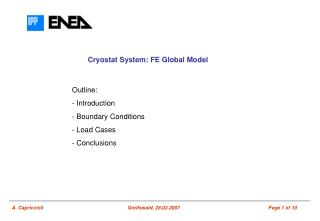
LASER and TIG welding ANSYS FE model for thermal and mechanical simulation (A. Capriccioli). ANSYS FE model for thermal and mechanical simulation. Introduction

E N D
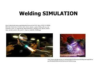
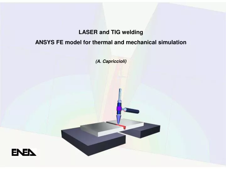
LASER and TIG welding ANSYS FE model for thermal and mechanical simulation (A. Capriccioli)
ANSYS FE model for thermal and mechanical simulation Introduction The aim of this first short document is the presentation of an ANSYS FE model for the thermal and mechanical simulation of welding processes. The main assumptions and features of the model are: • thermal analysis • the displacements of the parts, during the welding, don’t affect the thermal distribution of the parts themselves; • all the material properties are described as far as the metallic vapour; • c) convection and radiation effects are considered; • d) both Laser and TIG methodologies for root and/or filling weld are modelled; • e) the ANSYS element birth and death procedure is used; Click here A. Capriccioli Greifswald, May 2007
ANSYS FE model for thermal and mechanical simulation A. Capriccioli Greifswald, May 2007 Brief description of the model The first point is the description of the material properties (density, thermal conductivity, specific heat, enthalpy, thermal expansion coeff., Young modulus, yield strength, tensile strength, elongation, Poisson coeff.). In the actual model INCONEL 625 is used and the right thermal and mechanical characteristics are described up to the end of the transition from solid to liquid phase (heat of fusion) while the properties from all liquid to all vapour are roughly described.
ANSYS FE model for thermal and mechanical simulation A. Capriccioli Greifswald, May 2007
ANSYS FE model for thermal and mechanical simulation A. Capriccioli Greifswald, May 2007
ANSYS FE model for thermal and mechanical simulation A. Capriccioli Greifswald, May 2007 The geometry of the “caulker” is only for exposition purpose: in Fig.1 a standard V-shaped and a root zone for the Laser welding is shown. The width of the root seam is 0.5 mm (violet elements) and the height 4 mm. The total height of the plate is 17 mm. In Fig.2 a TIG caulker with a small rectangular root seam (2 mm) and a filling zone is shown. The welding parameters (Laser power or temperature of the “drop” of melted metal, welding speed, number of single-passes etc.) are arbitrarily fixed and they have to be set in accordance with experimental data. The same for the evaluation of the film coefficient (convection) and the material emissivity (radiation).
ANSYS FE model for thermal and mechanical simulation Film coeff. = 5.67 [W/(m^2·K)] Emissivity = 0.5 Metallography of an example of Laser welding (4 mm) Radiation zone Convection zone A. Capriccioli Greifswald, May 2007 TIG with filling material Dishing for leak test
ANSYS FE model for thermal and mechanical simulation A. Capriccioli Greifswald, May 2007
ANSYS FE model for thermal and mechanical simulation A. Capriccioli Greifswald, May 2007 • 2) mechanical analysis • the temperature distributions derive from the thermal analysis; • visco-elasto-plastic material is considered; • c) the ANSYS element birth and death procedure is used.
ANSYS FE model for thermal and mechanical simulation A. Capriccioli Greifswald, May 2007 Material Properties:
ANSYS FE model for thermal and mechanical simulation A. Capriccioli Greifswald, May 2007
ANSYS FE model for thermal and mechanical simulation A. Capriccioli Greifswald, May 2007 ·During the first load step of the mechanical analysis, the welding seam (in the sense of elements that will melt during the future process) are “killed”. ·To avoid penetration, proper contact elements connect the two pieces to weld. ·During the process, the temperature distributions are progressively loaded from the previous thermal analysis. ·Now, the temperature field is defined and the single element (or group of elements) of the welding seam “revives” (stress free) when its temperature reaches the melting temperature. ·As soon as a melted element ”revives”, some contact elements “die”: Click here Click here
ANSYS FE model for thermal and mechanical simulation A. Capriccioli Greifswald, May 2007 The point is now the description of the “shrinkage”: the system used is the definition of a new material (n°100 in the example) with the same thermal expansion of the basic material (n°1) but with a different Reference Temperature (melting point). This last material is assigned to the revived elements and when their temperature decreases the “shrinkage” takes effect. When the welding process ends, we can release the constraint of one of the two initial pieces and calculate the final displacements.
ANSYS FE model for thermal and mechanical simulation A. Capriccioli Greifswald, May 2007 Results The present set of results regard the thermal and mechanical analysis of a coupon test. The example of thermal analysis is reported in the previous slide 9 while some mechanical results and considerations are reported below: Further result of the simulation model is the identification of the constraints position with largest influence upon the plastic strain, minimizing the elastic energy stored in the system. The result of this choice will be the minimization of the elastic release at the end of the process.
ANSYS FE model for thermal and mechanical simulation A. Capriccioli Greifswald, May 2007 • Conclusions • At the end of these first activities the “vital few” seem to be: • a good description of the material properties and thermal boundary conditions; • a good description of the real constraints stiffness (blocking system); • the geometry of the “caulker” (“amount of energy” introduced in the system) and welding parameters (speed, power, etc.); • Other point is the “human factor”: the only system to reduce the variance of the final displacements are both the operator’s qualification and narrow ranges in the parameters sheet of the process equipment (a good process qualification, process control and incoming materials quality). • The “evaluation” of this component can derive only from a statistical analysis and the “range of uncertainty” has to be added to the FEM simulation results.