Download
1 / 13
130 likes | 379 Views
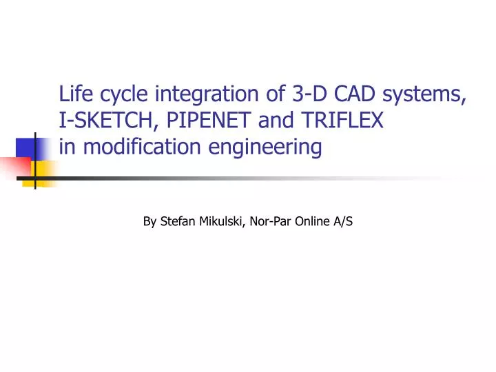
Life cycle integration of 3-D CAD systems, I-SKETCH, PIPENET and TRIFLEX in modification engineering. By Stefan Mikulski, Nor-Par Online A/S. The information workflow in modification engineering. 3-D CAD Plant Design System. Piping Stress Analysis (TRIFLEX). Fluid Flow Analysis (PIPENET).

E N D
Life cycle integration of 3-D CAD systems, I-SKETCH, PIPENET and TRIFLEXin modification engineering By Stefan Mikulski, Nor-Par Online A/S
The information workflowin modification engineering 3-D CAD Plant Design System Piping Stress Analysis(TRIFLEX) Fluid Flow Analysis(PIPENET)
The information transfer today • 3-D piping models made in Plant Design Systems exist. The piping department prints isometric drawings on paper • Isometric drawings are passed to mechanical department for Piping Stress Analysis in TRIFLEX Static • Isometric drawings are also used for Transient Fluid Flow Analysis in PIPENET Transient • Results from PIPENET Transient are passed on paper for Piping Stress Analysis in TRIFLEX Dynamic • The results of Piping Stress Analysis must be drawn manually in AutoCAD or MicroStation as Stress Isometrics • Results from PIPENET and TRIFLEX are passed on paper to Piping Department for updating the 3-D CAD models • All data transfer is done on paper or via non-intelligent CAD drawings
The drawbacks of the traditional information transfer • The data entry is made many times: • Very expensive “man-hour” approach. Engineers use most of time to enter data before they can focus on solving the engineering problem • Data inconsistency and mistakes cannot be avoided • Significant expenses are involved with cross-checking of the data between disciplines
PDSPDMSAutoPlant I-EXPORT I-SKETCH(ISOGEN) IDF/PCF Piping Specs I-CONVERT Smart Stress Iso PIPENET Standard ISK2PNS TRIFLEX Static ISK2PNT TRIFLEX Dynamic PIPENET Transient PTR2TRD Life Cycle Solution
Benefits of Life Cycle Solution • Single data entry. Data are used throughout disciplines and exchanged as digital files • Data consistent between all systems • Limited need for data cross-checking • Saved time and money
Smart Stress Iso Stress Isometric Drawings IDF/PCF I-SKETCH(ISOGEN) TRIFLEX Piping Specs Smart Stress Iso
Smart Stress Iso Workflow • The administrator “I-CONVERT”s all 3-D CAD Specs into I-SKETCH format *one time* • The engineer imports needed CAD Iso files into I-SKETCH. A piping system can be build out of isometric drawings • Smart Stress Iso transfers piping system models to TRIFLEX • Piping Stress Analysis is done in TRIFLEX. The engineer takes decisions about supports’ locations and functions and modifies the piping geometry as needed to meet Code Compliance • The engineer introduces the necessary changes to the model in I-SKETCH • Smart Stress Iso creates Stress Isometrics based on I-SKETCH geometry and TRIFLEX data to document modifications • The final piping system can be “I-EXPORT”ed from I-SKETCH to 3-D CAD system as new modified 3-D CAD model
Smart Stress Iso Benefits • Data are entered once, only when necessary • Piping Specs made once are further re-used • All data transfer is done by digital files. Data consistency is ensured • The need for consistency checking is greatly reduced • I-SKETCH is an inexpensive and very easy tool for modification work. You do not need to be CAD operator to work with I-SKETCH • The work time is used efficiently to solve problems not to enter data into TRIFLEX
PIPENET Transient toTRIFLEX Dynamic (PTR2TRD) • TRIFLEX Dynamic allows Time History Analysis (THA) • The required data for TRIFLEX THA are Time Functions and Nodal Excitations. It is very difficult to guess these data • PIPENET Transient calculates forces in a piping system based on transient fluid flow calculations • PTR2TRD application will transfer the PIPENET Transient force information to TRIFLEX Dynamic as Time Functions and Nodal Excitations
PTR2TRD Data Flow PIPENET Transient TRIFLEX Dynamic TRIFLEX Table Collection File PIPENETForce File (FRC) TRIFLEXNodal Excitations File PTR2TRD
PTR2TRD Workflow • Create and solve simulation problem in PIPENET Transient. Ask the program to generate Force File • Create a piping network in TRIFLEX and solve it in Static with Mode Shapes and Frequencies • Convert the PIPENET Force File to TRIFLEX Time Function (TTC) and Nodal Excitation (THA) files • Open TTC and THA files in TRIFLEX • Run Time History Analysis in TRIFLEX
PTR2TRD Benefits • Transient Fluid Flow analysis is the reliable tool to provide excitation information for Piping Stress Time History Analysis • Thousands of data points are transferred in seconds • The data consistency is ensured • PTR2TRD automatically transforms the coordinate systems and converts engineering units • Time and money are saved