Download
1 / 20
200 likes | 289 Views
DT Infrastructure: LV, HV, Gas, VDC. Mu Barrel Workshop 05 May 2011 A. Benvenuti (INFN Bologna). LV Connectors Saga. Tweaking LV connectors has become the prime cause for UX access requests

E N D
DT Infrastructure: LV, HV, Gas, VDC Mu Barrel Workshop 05 May 2011 A. Benvenuti (INFN Bologna)
LV Connectors Saga • Tweaking LV connectors has become the prime cause for UX access requests • Problems are usually manifested through a “temperature alert” for A3100, SC crates and MAOs (AC/DC power converters) or a “Vcon error” (power increase) for A3050 (MiniCrates) • Temperature scans ( Ignacio) with a thermal camera (and B Off) provide a good test for anomalies (“Hot Spots”) and have shown that also the A3009 (Front-End and Vcc power ) have hot connectors in spite of the low power consumption, typically 1.5 – 2. A at 5. V and 2.8 – 3.5 A at 2.5V • the AP connectors used in the DT LV system are a continuing source of problems in spite of: - splicing flexible cables to make the connection more resilient - adding lubricant
LV Problems Statistics (approximate) • In red, the modules that were changed (usually after repeated errors) some connectors were replaced by CAEN • In blue the modules that have given sporadic problems ( partial list for A3009) • In black modules that required at least one disconnect/connect intervention • Large number of problems in YB0 • Ignacio noticed a correlation of a hot spot in A3009 (MB3S01) and loss of a TRB
LV Connectors Saga (Radical Solution) • Solder pig tails on A3050 connectors that will mate with existing cables • Under investigation at CIEMAT (Cristina) and Padova (Matteo) • Main issue: solder pigtail without removing plastic sleeve • CMS week March 29 2011 • Matteo is confident that the soldering will not damage the pc board or components • The soldering can be done with the plastic protection in place • Damage to cover resulted from many tests NOT a risk during production • Proposal to modify a few modules, 1 or 2 sectors • Can be ready for June 20 TS ( Magnet OFF)
LV Connectors Saga (Radical Solution) • The pigtail length is the most critical item to define, probably 10-15 cm, might need more than one length to accommodate present situation • Unless absolutely necessary, the existing cables should not be modified • No strong objections from CAEN, contacted by Matteo, but would like to review the issue after the modification of 3-4 modules • If this fix is successful then it could be applied also to MAO and A3100 • With adequate planning and preparation, the pigtail soldering could be done during the end of the year TS • Decision needed at latest by end of October
HV Vagaries • A few chambers remain stuck or trip at the first HV step 1200/900/800 when switching HV ON from OFF • On March 29, 6 chambers tripped and 2 remained stuck • HV spikes indicate HV regulation problems at this step but mechanism is not obvious • Most of the chambers had given similar problems in the past but NOT always. • Often, the problem is not reproducible even in situ! • The usual fix is to: • Lower HV forstuck channel (w0 ) • Raise the HV to step 2 2000/1800/1200 for w1 • Raise w0 to 2000 V • Both channels go up to nominal without problems • HV ON from Standby operation is very robust
HV Vagaries • YB-1 MB1S09 started discharging strips and wires on all layers and SL • Obvious problem with positive HV regulation • Since there was an access ongoing I opted for changing the A877 board but the problem was on the A876 module in USC. • Module replaced, awaiting for test in B904 before shipping to CAEN • This failure mode already seen in ~4 modules, including bad regulation in negative HV • 16 Modules have been repaired, a few more than once • 2 units are “suspicious”, problem not seen at CAEN • the need for a more powerful test station and dedicated expert manpower is still with us both for LV and HV modules
HV Status ( May 2 ~ 14:00) More noisy chambers than usual • In more detail, at the layer Level: • Cathodes 23 (1 red) • Wires 5 (4 w0 + 1 w1 red) • Strips 0 • Total 28
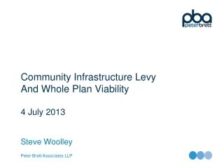
25-apr to 03-May YB-2 MB4S07 02-03 May • Fill 1755, May 2: • Stable beams at 06:15 dumped at 12:15 • Current spikes in Ibeams stopped after dump although cosmic run continued until ~9:30 May 3 • No spikes seen in other layers • Similar situation observed in other “noisy” chambers
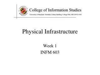
SL1 25-apr to 03-May YB+2 MB4S03 02-03 May
YB+2 MB4 S03 SL3 • Ibeam current spikes only in L1 • Some considerations: • Current spikes are certainly beam related • neutron induced is what comes to mind but it is not easy to explain why only few layers have spikes • Why cathodes and not wires? Maybe just positive ions…
Fill 1755 02-may-2011 Marina setup the monitoring of the HV current polling rates as a way to look forBeam related effects in the chambers for the first collisions in 2008 The difference in polling rates with cosmics for the wheels, especially YB+2, is not understood It is too early to make any quantitative statements from these observations HV in STANDBY Stable Beams Beam Dump Cosmics HV ON (Squeeze)
HV Status • But we have some behavioral problems: • YB+2 MB2S11 SL1 L3 w0 L2 Cathode spikes • YB+2 MB2S08 SL1 L4 w0 current spikes • YB-2 MB4S04 L4 w1, frequent ~10 uA current spikes that have recently became almost continuous. Channel in Standby, will put a TJB next week • YB0 MB4S04 SL1 L1 w0-cathode HV trip (recovered) followed few hours later by sustained w0-cathode current that fixed (burned) the problem
Difference between “Fresh Gas In” and “Output Flow” ~1000 liters/hour is due to a leak ( checked by Roberto Guida) Planned to be fixedduring January TS Still pending H2O analysis active only in YB0 Calibration dubious at best O2 content lower than we would like but difficult to adjust Gas chromatograph possibly ready end of May
The O2 analysis cells calibration drifted considerably for YB+2 and YB-2 • The cells were serviced ~ Apri 15, distance between points is ~ 55 hours • Reference gas is at 500 ppm O2, measures still deviate after cell servicing • Spread among common supply lines is larger than among common return • Need better control of calibrations • Gas group notified • O2 content should be ~150 ppm , asked for lower O2 in reference gas
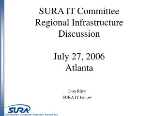
O2 Content (ppm) Measured from March 08 to April 26 • The O2 content spikes are ~ fixed features • The largest O2 value, 250 ppm, in YB0 MB1S02 does not affect data quality • We have to wait for the long shutdown to clean up the spikes • O2 time variation reflects observed analysis cells vagaries • No measurements of the N2 content yet, even for the common lines YB-2 YB0
The calibration is not meaningful • If the scale is correct then I worry that the H2O content is too high • I have not received any explanation for the peak at MB4S04, the O2 content is normal • Where is the H2O coming from? • Should we ask for a filter? • I have asked to move the device to another wheel H2O Content (ppm) measured from 08-mar to 26-apr
Gas Status (Concerns) • The gas purifiers were bypassed because the resulting O2 concentration was too low • At present the O2 concentration is controlled through the amount of fresh gas that is injected in the system, ~ 1800 liters/hour or ~13% of the gas flow , ~13700 l/h • Until the gas chromatograph is operational (and stable) we have no control of the N2 fraction • As luminosity increases we may need to increase the percentage of fresh gas and or increase the flow rate (with the present conditions it takes ~5 days to inject an entire volume of fresh gas) • This would reduce the amount of O2 increasing the risk of discharges • Consider adding a small fraction of O2 to the fresh gas (Roberto G. says it is easy, reliable and cheap ~5kCHF but….) • We need reliable gas analysis cells • What about H2O filtering 900+ ppm seem excessive to me but I am not an expert
6-VDC system running continuously, currently with the following gas matrix : • VDC1 -> YB-2 • VDC2 (spare) -> fresh gas (value higher by +0.4 µm/ns observed during intercalibration) • VDC3 -> YB-1 • VDC4 -> YB0 • VDC5 -> YB+1 • VDC6 -> YB+2 • some high values observed during CO2 • calibration in the gas analysis rack : • (we will set the gas flow to 0 during this • operation) VDC status and operation GerdFetchenhauer, CarstenHeidemann, Hans Reithler, Lars Sonnenschein, Daniel Teyssier Muon barrel workshop
VDC status and operation • 6-VDC data now available on the web based monitoring (thanks to Daniele, Marina, Zongru) • Current activities in Aachen : • setup a new test stand • produce 4 spare chambers • VDC7 to be upgraded Muon barrel workshop