Download
1 / 17
340 likes | 1.03k Views
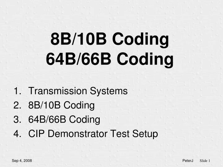
8B/10B Coding 64B/66B Coding. Transmission Systems 8B/10B Coding 64B/66B Coding CIP Demonstrator Test Setup. Flip Flop. D. Q. C. Transmission system General. Data. Clock. @ 1 Gbps = 1 ns = 20 cm. Flip Flop. D. Q. C. ?. ?. ?. ?. Transmission system Propagation Delay. Data.

E N D
8B/10B Coding64B/66B Coding • Transmission Systems • 8B/10B Coding • 64B/66B Coding • CIP Demonstrator Test Setup
Flip Flop D Q C Transmission systemGeneral Data Clock @ 1 Gbps = 1 ns = 20 cm
Flip Flop D Q C ? ? ? ? Transmission systemPropagation Delay Data Clock Unequal propagation delay 10 cm @ 1 Gbps
Flip Flop D Q C Transmission systemClock Data Recovery Data CDR PLL Clock Combine Clock and Data! If there are enough edges in the data then the clock can be recovered from the data using a PLL PLL
Code Properties • Provide enough edges in the data to enable Clock Recovery
Flip Flop D Q C Transmission systemReceiver Threshold Data CDR Clock Receiver Threshold refers to “Ground” which must be the same potential as “Ground” at the transmitter! Jitter!
Flip Flop D Q C Transmission Use Differential signalling! Data CDR Clock Icm Receiver Threshold is halfway positive and negative signal Use AC Coupling Capacitors… Need DC Balance! Common mode voltage difference between transmitter and termination at the receiver can result in excessive currents
DC Balance 1 0 1 0 1 1 0 1 0 1 1 1 1 ? 0 1 1 1 1 1 Define a maximum Run Length Sent equal amount of ‘1’s and ‘0’s (Running Disparity)
Receiver Automatic Gain Control Gain Time Gain Again: maximum Run Length Time
Code Properties • Provide enough edges in the data to enable Clock Recovery • Maximum Run Length and DC Balance
8B/10B coding • Maximum run length = 5 • Running Disparity => DC Balance • 8 bits => 256 different values • 10 bits => 1024 different values • 8B10B code is built out of: (5 to 6 bit code) + (3 to 4 bit code)
8B/10B coding • Not all 1024 values are useful. • For example “0100000011” has run length 6 • For most of the 256 (8B) values a positive and a negative 10B value is selected depending on the “Current Running Disparity” • For example: D7.0 = 1110001011 (Current RD-) D7.0 = 0001110100 (Current RD+) • So about 512 useful values are selected from 1024… • There are still a few codes left!
8B/10B coding table • 256 “Data” Characters:
8B/10B coding table • There were still a few codes left! • 12 “Special” K Characters: Comma Characters “The only patterns that have 5 consecutive ‘1’s or ‘0’s
8B/10B code “K” Characters • Comma characters K28.1/K28.5/K28.7 are used word alignment 010101001101100111000001010110111010010100100111010011001001110100111001 010101001101100111000001010110111010010100100111010011001001110100111001 D0.0 ??.? K28.5 D16.2 D31.3 D11.3 • Create “ordered sets” • For example Fibre Channel Start Of Frame (SOF) = K28.5/D21.5/D23.0/D23.0 • K30.7 = Error Propagate • K28.3 = Carrier Extend
8B/10B code properties • Provide enough edges in the data to enable Clock Recovery • Maximum Run Length and DC Balance • Add special characters • Comma for word alignment • Control characters