Download
1 / 65
660 likes | 837 Views
Electron Diffraction of 2D crystals - principle and data collection. Yifan Cheng. Department of Biochemistry and Biophysics University of California San Francisco. August 15-19, 2011 TEMIMPS 2DX Workshop at UW Seattle. Electron Crystallography of 2D crystal.

E N D
Electron Diffraction of 2D crystals- principle and data collection Yifan Cheng Department of Biochemistry and Biophysics University of California San Francisco August 15-19, 2011 TEMIMPS 2DX Workshop at UW Seattle
Electron Crystallography of 2D crystal Electron diffraction and image of 2D crystal are two integrated parts of electron crystallography: * Image of a 2D crystal provides both phases and amplitudes of each reflections from the crystal; However the amplitude is modified by CTF, envelope functions, ... etc. In principle, one can determine the structure of a 2D crystal using image only, with both phases and amplitudes determined directly from images. But in practice this is very difficult, particular towards atomic resolution. * Electron diffraction provides accurate amplitudes of each reflections, but without any phase information, same as in the x-ray crystal. One cannot determine the structure of a 2D crystal only from diffraction, unless the phases can be determined by other method, such as molecular replacement, ... etc.
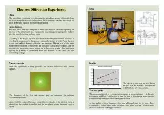
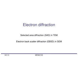
Outlines 1) Principle of electron diffraction; 2) How to set up the microscope for diffraction; 3) Collecting good diffraction patterns; 4) Data processing; 5) Recording medium: CCD/Image Plate/Film; 6) What’s more to think about; * In all the discussion here, we assume that your crystal is suitable for the electron diffraction: you have already got “perfect” crystals with sufficient large size, and you can make “perfect” grids using “perfect” carbon film on a “perfect” Mo grid. Under such assumption, we will be discussing how to get “perfect” electron diffraction pattern.
Outlines 1) Principle of electron diffraction; 2) How to set up the microscope for diffraction; 3) Collecting good diffraction patterns; 4) Data processing; 5) Recording medium: CCD/Image Plate/Film; 6) What’s more to think about;
A simplified electron optic system in an electron microscope Electron source Condenser lens C1 Condenser lens C2 Condenser aperture specimen Objective lens Back focal plane Objective aperture Back image plane Select area aperture
Additional lens in the electron microscope Projection lens system Image shift/diffraction shift coils viewing screen/camera
Electromagnetic lens * The focal length of a electromagnetic lens can be easily adjusted by changing the lens current. * Switching between image and diffraction modes is done by pressing a button in the microscope.
Image mode Clathrin coat Image mode * Intermediate/projection lens system was set to correspond the camera to the back-image-plan.
Diffraction mode from bacteriorhodopsin diffraction mode * Intermediate/projection lens system was set to correspond the camera to the back-image-plan.
Image/diffraction formation • The image/diffraction formation in the electron microscope can be treated as two separate processes: • The interaction of the incident beam with the specimen, described by the weak-phase object approximation, which is the theory used mostly to describe the image formation of thin specimen with light elements, such as a biological sample. • The propagation of the electron beam from exit plane of the specimen to the back focal plan (diffraction) and back image plane (image) of the objective lens.
Weak-phase object approximation Suppose: 1) the specimen is very thin so that can be approximated by ; 2) both in-coming and exiting beams are parallel beams; This is a highly simplified theory based on the so-call weak-phase object, which is a very thin specimen formed mostly by low- and medium-weight molecules.
Diffraction/Image formation At exit plane of specimen: At back focal plane: At back image plane: focal plane image plane
At back focal plan: The plane wave ψ’ of exit-beam travel through objective lens to the back focal plane. The wave function at back focal plane of the objective lens is the Fourier transform of the exit wave: (7) However the lens aberration and defocusing generate an extra phase shift to the scattered beam: (8) Together with the aperture function A(k) the wave function at back focal plane will become: (9)
where is the structure factor (amplitude) of reflection (h,k) from a 2D crystal. Electron Diffraction At back focal plane: Intensity at back focal plane (diffraction intensity) is: Therefore, the diffraction intensity is not affected by the CTF. CTF cannot be measured directly from diffraction. In case of a crystal (or 2D crystal):
What about image? Together with the aperture function A(k) the wave function at back focal plane will become: (9) Then, the wave function in the back image plane of the lens is the reverse Fourier transform of the wave function at back focal plane (⊗ is for convolution): (10) The observed intensity in the image is then: (11)
Fourier transform provide amplitude Fourier transform of the image also gives amplitude as well as phases of a 2D crystal. Both are modulated by the CTF, it is easier to correct for the modulation to the phase (phase flipping), but less accurate for the amplitude correction. In electron diffraction: Intensity is the square of structure factor, without CTF modification. But there is no phase information, thus not sensitive to the specimen movement (drift).
Collecting diffraction pattern is easier than collecting image Diffraction pattern does not contain phase information, thus it is insensitive to any instability of stage/specimen. “Probably the best electron diffraction pattern of frozen hydrated catalase obtained in 1970’s.” Taylor and Glaeser (2008) “Retrospective on the early development of cryoelectron microscopy of macromolecules and a prospective on opportunities for the future” Journal of Structural Biology
Outlines 1) Principle of electron diffraction; 2) How to set up the microscope for diffraction; 3) Collecting good diffraction patterns; 4) Data processing; 5) Recording medium: CCD/Image Plate/Film; 6) What’s more to think about;
Electron optics of Low-Dose imaging Beam shift Image shift SEARCH FOCUS EXPOSURE
Setup for diffraction * Using LowDose procedure. Over focused diffraction for SEARCH, focused diffraction with parallel incident beam for diffraction. * To maintain a parallel beam, the choice of sizes of incident beam on specimen is limited, but can be changed by adjusting Spot Size and Condenser Aperture size.
Setup for diffraction * Locate an area where there is no crystal to destroy.
Setup for diffraction * Locate an area where there is no crystal to destroy. * Correlate the SEARCH mode and EXPOSURE mode.
Setup for diffraction * Locate an area where there is no crystal to destroy. * Correlate the SEARCH mode and EXPOSURE mode. * Move a crystal into the pointer.
Setup for diffraction * Locate an area where there is no crystal to destroy. * Correlate the SEARCH mode and EXPOSURE mode. * Move a crystal into the pointer. * Insert the Selected Area Aperture to the selected crystal.
Setup for diffraction * Locate an area where there is no crystal to destroy. * Correlate the SEARCH mode and EXPOSURE mode. * Move a crystal into the pointer. * Insert the Selected Area Aperture to the selected crystal. * Record diffraction in the EXPOSURE mode.
Setup for diffraction * Locate an area where there is no crystal to destroy. * Correlate the SEARCH mode and EXPOSURE mode. * Move a crystal into the pointer. * Insert the Selected Area Aperture to the selected crystal. * Record diffraction in the EXPOSURE mode. * Back to the SEARCH mode. Move the specimen to another crystal.
Setup for diffraction * Locate an area where there is no crystal to destroy. * Correlate the SEARCH mode and EXPOSURE mode. * Move a crystal into the pointer. * Insert the Selected Area Aperture to the selected crystal. * Record diffraction in the EXPOSURE mode. * Back to the SEARCH mode. Move the specimen to another crystal. Search (D) Focus (I) Exposure (D)
A nice electron diffraction pattern Liquid Helium microscope @ Kyoto University Electron diffraction of bR @ pH10 2.5Å 0°
Outlines 1) Principle of electron diffraction; 2) How to set up the microscope for diffraction; 3) Collecting good diffraction patterns; 4) Data processing; 5) Recording medium: CCD/Image Plate/Film; 6) What’s more to think about;
A nice electron diffraction pattern A “perfect” electron diffraction pattern comes with: * sharp diffraction spots towards high resolution * no mixture of spots from different crystals * symmetrical background distribution - for globe background subtraction * good symmetry: intensities of Friedel-pair are equal - good Rfriedel * spots are sufficient apart - easy for background substation * optimized exposure time to avoid over flow of central spot * ... ... ... ... 0°
What do these requirements mean? • A “perfect” electron diffraction pattern comes with: • * sharp diffraction spots towards high resolution • parallel beam, well focused diffraction pattern • * no mixture of spots from different crystals • using selected area aperture • * symmetrical background distribution - for globe background subtraction • good focus in real space • * good symmetry: intensities of Friedel-pair are equal - good Rfriedel • good focus in real space, proper recording medium (CCD) • * spots are sufficient apart - for background substation • select proper camera length, using large CCD camera (8Kx8K), using detector with high sensitivity and dynamic range • * optimized exposure time to avoid over flow of central spot • LowDose procedure, exposure time ... • * ... ... ... ... • ... ... ... ...
Good sample preparation Tamir Gonen
Using beam stop Tamir Gonen
Exposure time Tamir Gonen
Sharp diffraction spots require parallel incident beam and diffraction focusing
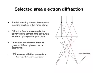
Using selected area aperture to record diffraction from the selected crystal back focal plane back image plane Specimen
Using selected area aperture to record diffraction from the selected crystal back focal plane back image plane Specimen
Symmetrical background * background in a diffraction pattern comes from non-crystal background and electron with energy lose.
Symmetrical background * background in a diffraction pattern comes from non-crystal background and electron with energy lose. * background is described as symmetrical background.
Symmetrical background * background in a diffraction pattern comes from non-crystal background and electron with energy lose. * background is described as symmetrical background. * and non-symmetrical background, which is influenced by the focus of objective lens.
Symmetrical background * background in a diffraction pattern comes from non-crystal background and electron with energy lose. * background is described as symmetrical background. * and non-symmetrical background, which is influenced by the focus of objective lens. * non-symmetrical background influences the Rfriedel value.
Symmetrical background * This is more important for tilted specimen, such as this one from 60 degree tilted specimen. 60°
Symmetrical background * This is more important for tilted specimen, such as this one from 60 degree tilted specimen. 60°
Symmetrical background * This is more important for tilted specimen, such as this one from 60 degree tilted specimen. 60°
Symmetrical background * This is more important for tilted specimen, such as this one from 60 degree tilted specimen. * If the image in real space is out of focus, the asymmetrical background will be very asymmetrical.
Other things to consider * Camera length: camera length is like magnification of diffraction pattern. The larger the camera length, the wider diffraction spots separate from each other, and better for background subtraction and spot integration. (The size of camera is the limiting factor.) * Dose: follow low dose practice to minimize radiation damage to the 2D crystals. * Use beam-stop to block the central direct beam and prevent overflow. * Exposure time is often depends on the size of the crystal (larger crystal using less exposure time), SA aperture, and beam-stop size. * Long exposure (high dose) better for high resolution spots but with a higher temperature factor.
Outlines 1) Principle of electron diffraction; 2) How to set up the microscope for diffraction; 3) Collecting good diffraction patterns; 4) Data processing; 5) Recording medium: CCD/Image Plate/Film; 6) What’s more to think about;
Processing electron diffraction pattern * Four steps: 1) Determine lattice, tilt axis and tilt angles.