Download
1 / 41
430 likes | 653 Views
Viewing With OpenGL. Courtesy of Drs. Carol O’Sullivan / Yann Morvan Trinity College Dublin. OpenGL Geometry Pipeline. MODELVIEW matrix. PROJECTION matrix. perspective division. viewport transformation. original vertex. final window coordinates. normalised device coordinates

E N D
Viewing With OpenGL Courtesy of Drs. Carol O’Sullivan / Yann Morvan Trinity College Dublin
OpenGL Geometry Pipeline MODELVIEW matrix PROJECTION matrix perspective division viewport transformation original vertex final window coordinates normalised device coordinates (foreshortened) 2d projection of vertex onto viewing plane vertex in the eye coordinate space
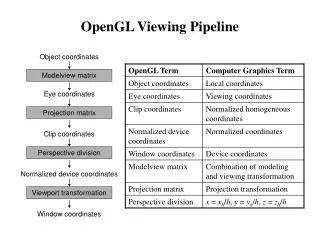
Summary - 1 • Object Coordinates are transformed by the ModelView matrix to produce Eye Coordinates. • Eye Coordinates are transformed by the Projection matrix to produce Clip Coordinates. • Clip Coordinates X, Y, and Z are divided by Clip Coordinate W to produce Normalized Device Coordinates. • Normalized Device Coordinates are scaled and translated by the viewport parameters to produce Window Coordinates.
Summary - 2 • Object coordinates are the raw coordinates you submit to OpenGL with a call to glVertex*() or glVertexPointer(). They represent the coordinates of your object or other geometry you want to render. • Many programmers use a World Coordinate system. • Objects are often modeled in one coordinate system, then scaled, translated, and rotated into the world you're constructing. • World Coordinates result from transforming Object Coordinates by the modelling transforms stored in the ModelView matrix. • However, OpenGL has no concept of World Coordinates. World Coordinates are purely an application construct.
Summary - 3 • Eye Coordinates result from transforming Object Coordinates by the ModelView matrix. • The ModelView matrix contains both modelling and viewing transformations that place the viewer at the origin with the view direction aligned with the negative Z axis. • Clip Coordinates result from transforming Eye Coordinates by the Projection matrix. • Clip Coordinate space ranges from -Wc to Wc in all three axes, where Wc is the Clip Coordinate W value. OpenGL clips all coordinates outside this range.
Summary - 4 • Perspective division performed on the Clip Coordinates produces Normalized Device Coordinates, ranging from -1 to 1 in all three axes. • Window Coordinates result from scaling and translating Normalized Device Coordinates by the viewport. • The parameters to glViewport() and glDepthRange() control this transformation. • With the viewport, you can map the Normalized Device Coordinate cube to any location in your window and depth buffer.
The Camera System • To create a view of a scene we need: • a description of the scene geometry • a camera or view definition • Default OpenGL camera is located at the origin looking down the -z axis. • The camera definition allows projection of the 3D scene geometry onto a 2D surface for display. • This projection can take a number of forms: • orthographic (parallel lines preserved) • perspective (foreshortening): 1-point, 2-point or 3-point • skewed orthographic
Camera Types • Before generating an image we must choose our viewer: • The pinhole camera model is most widely used: • infinite depth of field (everything is in focus) • Advanced rendering systems model the camera • double gauss lens as used in many professional cameras • model depth of field and non-linear optics (including lens flare) • Photorealistic rendering systems often employ a physical model of the eye for rendering images • model the eyes response to varying brightness and colour levels • model the internal optics of the eye itself (diffraction by lens fibres etc.)
Modeling the Eye’s Response Adaptation (see aside on Eye) Glare & Diffraction
Camera Systems A camera model implemented in Princeton University (1995)
Viewing System view frustrum • We are only concerned with the geometry of viewing at this stage. • The camera’s position and orientation define a view-volume or view-frustrum. • objects completely or partially within this volume are potentially visible on the viewport. • objects fully outside this volume cannot be seen clipped clipping planes clipped
Camera Models • Each vertex in our model must be projected onto the 2D camera viewport plane in order to be displayed on the screen. • The CTM is employed to determine the location of each vertex in the camera coordinate system: • We then employ a projection matrix defined by GL_PROJECTION to map this to a 2D viewport coordinate. • Finally, this 2D coordinate is mapped to device coordinates using the viewport definition (given by glViewport()).
Camera Modeling in OpenGL ® camera coordinate system viewport coordinate system device/screen coordinate system glMatrixMode(GL_MODELVIEW) ... glViewport(0,0,xres,yres) glMatrixMode(GL_PROJECTION) ...
3D 2D Projection • Type of projection depends on a number of factors: • location and orientation of the viewing plane (viewport) • direction of projection (described by a vector) • projection type: Projection Perspective Parallel 1-point Orthographic 2-point Axonometric 3-point Oblique
Parallel Projections orthographic axonometric oblique
Orthogonal Projections • The simplest of all projections, parallel project onto view-plane. • Usually view-plane is axis aligned (often at z=0)
Orthogonal Projections • The result is an orthographic projection if the object is axis aligned, otherwise it is an axonometric projection. • If the projection plane intersects the principle axes at the same distance from the origin the projection is isometric.
Parallel Projections in OpenGL glOrtho(xmin, xmax, ymin, ymax, zmin, zmax); Note: we always view in -z direction need to transform world in order to view in other arbitrary directions.
Perspective Projections • Perspective projections are more complex and exhibit fore-shortening (parallel appear to converge at points). • Parameters: • centre of projection (COP) • field of view (q, f) • projection direction • up direction
Perspective Projections 3-point perspective 1-point perspective 2-point perspective
Perspective Projections Consider a perspective projection with the viewpoint at the origin and a viewing direction oriented along the positive -z axis and the view-plane located at z = -d a similar construction for xp d y yp -z divide by homogenous ordinate to map back to 3D space
PROJECTION matrix perspective division Perspective Projections Details Flip z to transform to a left handed co-ordinate system increasing z values mean increasing distance from the viewer.
Perspective Projection • Depending on the application we can use different mechanisms to specify a perspective view. • Example: the field of view angles may be derived if the distance to the viewing plane is known. • Example: the viewing direction may be obtained if a point in the scene is identified that we wish to look at. • OpenGL supports this by providing different methods of specifying the perspective view: • gluLookAt, glFrustrum and gluPerspective
Perspective Projections glFrustrum(xmin, xmax, ymin, ymax, zmin, zmax);
glFrustrum • Note that all points on the line defined by (xmin,ymin,-zmin) and COP are mapped to the lower left point on the viewport. • Also all points on the line defined by (xmax,ymax,-zmin) and COP are mapped to the upper right corner of the viewport. • The viewing direction is always parallel to -z • It is not necessary to have a symmetric frustrum like: • Non symmetric frustrums introduce obliqueness into the projection. • zmin and zmax are specified as positive distances along -z glFrustrum(-1.0, 1.0, -1.0, 1.0, 5.0, 50.0);
Perspective Projections gluPerspective(fov, aspect, near, far);
gluPerspective • A utility function to simplify the specification of perspective views. • Only allows creation of symmetric frustrums. • Viewpoint is at the origin and the viewing direction is the -z axis. • The field of view angle, fov, must be in the range [0..180] • apect allows the creation of a view frustrum that matches the aspect ratio of the viewport to eliminate distortion.
Lens Configurations 10mm Lens (fov = 122°) 20mm Lens (fov = 84°) 35mm Lens (fov = 54°) 200mm Lens (fov = 10°)
Positioning the Camera • The previous projections had limitations: • usually fixed origin and fixed projection direction • To obtain arbitrary camera orientations and positions we manipulate the MODELVIEW matrix prior to creation of the models. This positions the camera w.r.t. the model. • We wish to position the camera at (10, 2, 10) w.r.t. the world • Two possibilities: • transform the world prior to creation of objects using translatef and rotatef: glTranslatef(-10, -2, -10); • use gluLookAt to position the camera with respect to the world co-ordinate system: gluLookAt(10, 2, 10, … ); • Both are equivalent.
Positioning the Camera gluLookAt(eyex, eyey, eyez, lookx, looky, lookz, upx, upy, upz); theta phi equivalent to: glTranslatef(-eyex, -eyey, -eyez); glRotatef(theta, 1.0, 0.0, 0.0); glRotatef(phi, 0.0, 1.0, 0.0);
The Viewport • The projection matrix defines the mapping from a 3D world co-ordinate to a 2D viewport co-ordinate. • The viewport extents are defined as a parameter of the projection: • glFrustrum(l,r,b,t,n,f) • gluPerspective(fv,a,n,f) (r,t,-n) (l,b,-n) (w,h,-n) (-w,-h,-n)
The Viewport • We need to associate the 2D viewport co-ordinate system with the window co-ordinate system in order to determine the correct pixel associated with each vertex. normalised device co-ordinates window co-ordinates
Viewport to Window Transformation • An affine planar transformation is used. • After projection to the viewplane, all points are transformed to normalised device co-ordinates: [-1…+1, -1…+1] • glViewport used to relate the co-ordinate systems: glViewport(int x, int y, int width, int height);
Viewport to Window Transformation • (x,y) = location of bottom left of viewport within the window • width,height = dimension in pixels of the viewport • normally we re-create the window after a window resize event to ensure a correct mapping between viewport and window dimensions: static void reshape(int width, int height) { glViewport(0, 0, width, height); glMatrixMode(GL_PROJECTION); glLoadIdentity(); gluPerspective(85.0, 1.0, 5, 50); }
Aspect Ratio • The aspect ratio defines the relationship between the width and height of an image. • Using gluPerspective an viewport aspect ratio may be explicitly provided, otherwise the aspect ratio is a function of the supplied viewport width and height. • The aspect ratio of the window (defined by the user) must match the viewport aspect ratio to prevent unwanted affine distortion: aspect ratio = 0.5 aspect ratio = 1.25
Multiple Projections • To help 3D understanding, it can be useful to have multiple projections available at any given time • usually: plan (top) view, front & left or right elevation (side) view Perspective Top Front Right
// top left: top view glViewport(0, win_height/2, win_width/2, win_height/2); glMatrixMode(GL_PROJECTION); glLoadIdentity(); glOrtho(-3.0, 3.0, -3.0, 3.0, 1.0, 50.0); gluLookAt(0.0, 5.0, 0.0, 0.0, 0.0, 0.0, 0.0, 0.0, -1.0); glMatrixMode(GL_MODELVIEW); glLoadIdentity(); glCallList(object); // top right: right view glViewport(win_width/2, win_height/2, win_width/2, win_height/2); glMatrixMode(GL_PROJECTION); glLoadIdentity(); glOrtho(-3.0, 3.0, -3.0, 3.0, 1.0, 50.0); gluLookAt(5.0, 0.0, 0.0, 0.0, 0.0, 0.0, 0.0, 1.0, 0.0); glMatrixMode(GL_MODELVIEW); glLoadIdentity(); glCallList(object); // bottom left: front view glViewport(0, 0, win_width/2, win_height/2); glMatrixMode(GL_PROJECTION); glLoadIdentity(); glOrtho(-3.0, 3.0, -3.0, 3.0, 1.0, 50.0); gluLookAt(0.0, 0.0, 5.0, 0.0, 0.0, 0.0, 0.0, 1.0, 0.0); glMatrixMode(GL_MODELVIEW); glLoadIdentity(); glCallList(object); // bottom right: rotating perspective view glViewport(win_width/2, 0, win_width/2, win_height/2); glMatrixMode(GL_PROJECTION); glLoadIdentity(); gluPerspective(70.0, 1.0, 1, 50); gluLookAt(0.0, 0.0, 5.0, 0.0, 0.0, 0.0, 0.0, 1.0, 0.0); glMatrixMode(GL_MODELVIEW); glLoadIdentity(); glRotatef(30.0, 1.0, 0.0, 0.0); glRotatef(Angle, 0.0, 1.0, 0.0); glCallList(object); Sample Viewport Application