Download
1 / 29
370 likes | 952 Views
Ionic ceramic conductors. Solid Oxide Fuell Cells (SOFCs). Fuel cells. Generalities.

E N D
Ionic ceramic conductors. Solid Oxide Fuell Cells (SOFCs)
Fuel cells. Generalities Fuel cells (FCs): electrochemical devices for the direct conversion of chemical energy in electricity by redox reactions at the electrodes. Differently from batteries, FCs are open systems wich allow continuous supply of the reactants (oxygen/air at cathode, hydrogen/hydrocarbons at anode). • First application: power generation in space (Gemini & Apollo missions). • Current applications (still under development): • - Miniaturized power generation for portable electronic devices (notebooks, tablets, mobile phones, military applications.) • - Small to average size cogeneration systems (hot water + electricity). • Large scale power generation and car engines: no longer a target. • Advantages: better conversion efficiency (60%; >90% in cogeneration) in comparison to combustion engines and gas turbines (25%): lower environmental impact. Steady power. • Fully clean energy production using H2 as fuel: still a dream. • Drawbacks: still suffer of reliability issues and short operation time (target: 40000 h/5y). Replacement of combustion engines requires hybrid electrochemical devices
Alkaline Polymeric electrolyte membrane Direct methanol Phosphoric acid Molten carbonate Solid oxide Fuel cells. Existing technologies Anode: negative electrode associated with fuel (H2) oxidation and release of electrons into the external circuit (porous). Cathode: positive electrode associated with reduction of the oxidant (O2) that gains electrons from the external circuit (porous). Electrolyte: Material that provides pure ionic conductivity and physically keep separated fuel and oxidant (dense).
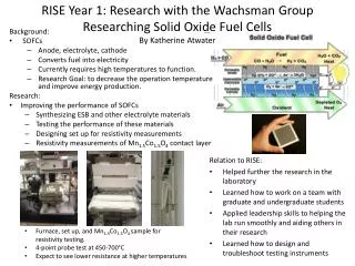
Solid Oxide Fuel Cells (SOFCs). Principles G° = -236 kJ/mol (Gibbs’ free energy) (net useful energy available) The basic reaction in SOFC is: fuel oxidant exhaust n: number of electrons per mol of product F: Faraday constant (charge of 1 equiv. of electrons) E: cell reaction voltage (OCV: open circuit voltage) (electromotive force of the cell reaction) E = 1.23 V in standard conditions E 1.0 V using air and typical reforming gas (25% H2) Nernst’s equation: G=-nFE If hydrocarbons are used as fuel they must be converted to hydrogen by a reforming reaction. SOFCs can be directly feeded with hydrocarbons. Reforming of hydrocarbons is promoted at the anodic size of SOFCs using a suitable catalyst due to the high operation temperature. Electrode reactionsAnodeCathode
SOFCs. Polarization phenomena G=-nFE Equilibrium conditions. Only describes the maximum available energy/voltage (OCV) In practice, when the current flows through the circuit, there is a voltage drop due the polarization of the electrodes : = EOCV – ET = 0.3-0.4 V ET = 0.6 – 0.7 V Polarization is determined by irreversibilities (losses) and kinetic limitations. Three effects: Activation polarization: kinetics of electrochemical redox reactions at the electrolyte/electrode interface; Ohmic polarization: resistance of cell components and resistance due to contacts problems; = RI Concentration polarization: arises from limited mass transport capabilities (electrolyte). Typical operating conditions: 0.7 V, 500 mA cm-2 Power = V I = 0.35 W cm-2 Stack of 29 cells, 10x10 cm2: 1kW
Oxide-ion conducting electrolyte. Most research and pilot modules are focused on this approach. Proton conducting electrolyte. Lower working temperature but problems of chemical stability and durability still to be solved. SOFCs and electrolytes . Two different approaches
Planar design Requirements for SOFC materials Very high operation temperatures: 800 (today)-1000°C (1990s). Severe requirements for materials: - Chemically stable in oxidizing and reducing atmospheres; - Absence of interface reaction/diffusion (chemical compatibility); - Similar thermal expansion coefficients; - Dimensional stability in the presence of chemical gradients; Resistance to thermal cycling and stresses SOFCs. Architecture and material requirements Tubular design
SOFCs. Different SOFC architectures Anode supported cell Cathode supported cell Interconnects supported cell Porous substrate (metal foam) supported cell
SOFCs. From single cells to stacks Examples of planar SOFC stacks
Elements of a micro-tubular SOFC Siemens Westinghouse 100-kW SOFC–CHP power system SOFCs. Tubular SOFCs
Advanced SOFC concept Functional layer: optimized microstructure for long TPB Support layer: coarse porosity and mechanical resistance SOFCs. Materials • Present research mainly focused on lowering the working temperature below 800°C to improve reliability, increase life time (target: 40000 h) and reduce costs. • Lower temperatures determine: • >Slow down of the kinetic processes; • >Increase electrode polarization and polarization resistance; • LSM: 1 cm2 (1000°C) 1000 cm2 (500°C) • >Increase electrolyte resistance; • >Reduction of cell voltage, • Efficient low-temperature SOFCs require optimization of materials and new combinations of electrolyte and electrode materials for: • Rapid ion transport (thin electrolytes, new electrolytes); • Fast reactions at the electrodes (new cathode materials, optimized microstructure); • Efficient electrocatalysis of oxygen reduction and fuel oxidation
SOFCs. Materials Kinetic processes at the anode Three-phase percolating composite gas-Ni-YSZ. The hydrogen oxidation reaction occurs at the triple phase boundary (TPB) gas – Ni – YSZ and involves many elementary steps: > Hydrogen adsorption > Surface diffusion > Charge transfert > Water desorption The reaction kinetics is limited by the length of the TPB. TPB length is increased by the use of cermets. Microstructure optimization (small grains, high number of small pores leads to higher performance but increased sensitivity to carbon deposition. With pure Ni or noble metal electrodes, hydrogen oxidation only occurs at the metal/YSZ interface rather than in the whole anode volume.
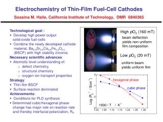
Kinetic processes at the cathode SOFCs. Materials Kinetic processes: (1) Gas diffusion; (2) O2 adsorption and dissociation; (3) O reduction (4) Solid-state diffusion; (5) Incorporation in the electrolyte at the interface or TPB; Oxygen diffusion coefficient Good electron conductor Poor oxygen conductor Electrode resistance. Determined by microstructure (tortuosity, porosity, surface area) Surface exchange velocity. Determined by electrode reaction kinetics. Good electron conductor Good oxygen conductor
SOFCs Overeview of materials and requirements for SOFCs components
Thin electrolyte layer on a anode-supported cell Supporting Ni-YSZ anode with graded porosity 1 mm Examples of cathodes Electrolyte-supported SOFC SOFCs. Materials
1000K 700K Oxide-ion conductors Proton conductors SOFCs. Electrolytes Minimum working temperature for electrolytes (thickness: 10 m; S = 10-2 Scm-1) YSZ: 700 °C; GDC (CGO) and LSGM: 550°C Y:BaZrO3: 400°C; Y:BaCeO3: 550°C YSZ: YxZr1-xO2- Good oxygen conductivity; High stability and good mechanical properties; Compatible with Ni/NiO electrodes; Reactivity with La-containing perovskites (formation of resistive La2Zr2O7); GDC: GdxCe1-xO2- Highest conductivity at low temperature; Good chemical compatibility with new cobalt-containing cathodes (La0.6Sr0.4Co0.2Fe0.8O3). Electronic conductivity in reducing atmosphere for T > 500°C. LSGM: La1-xSrxGa1-yMgyO3 Higher oxygen conductivity than YSZ Better compatibility with La-containing perovskites; Reactivity with Ni/NiO electrodes. Instability in moist H2. Y:BaZrO3 High bulk conductivity, resistive grain boundaries; Y:BaCeO3 Good conductivity, thermodynamic instability in the presence of CO2
625K 1670K 1000K 625K 1670K 1000K Doped electrolytes Pure electrolytes with order-disorder transition SOFCs. Electrolytes Oxide-ion conductors Ordering phase transitions Use of some electrolytes with high conductivity is limited by phase transitions. The conductive phase is the high-temperature disordered modification. The high temperature phase can be stabilized by appropriate dopants but problems related to instability in reducing conditions and reactivity with electrodes remain.
A B Saddle point configuration B SOFCs. Electrolytes Oxygen diffusion in perovskites (LaBO3, B=Fe, Cr, Ni, Mn )
YxZr1-xO2- Cubic Zr O Tetragonal Zr3Y4O12 Monoclinic Fluorite structure Y2O3 SOFCs. Electrolytes Oxide-ion conductors Optimal compositions: YSZ – YxZr1-xO2- x 0.16 (8 mol.% Y2O3) SSZ – ScxZr1-xO2- x 0.2 (8-12 mol% Sc2O3) (highest conductivity, low defect association energy)
SOFCs. Electrolytes Oxide-ion conductors Grain boundary oxygen vacancy segregation in YSZ Real vs. simulated lattice Oxygen column occupancy Calculated gb potential barrier: 0.5-1.2 V Column intensity ratio
EELS analysis Small angle tilt boundary Column intensity SOFCs. Electrolytes Oxide-ion conductors Grain boundary oxygen vacancy segregation in YSZ
MxZr1-xO2-δ Conductivity (S cm-1) Conductivity (S cm-1) M2O3 mol. % YxCe1-xO2-δ CaxCe1-xO2-δ Y2O3 mol. % Conductivity (S cm-1) x102 CaO mol. % SOFCs. Electrolytes Oxide-ion conductors
Prevails at high T and low dopant conc. Trivalent dopant Hm : enthalpy of migration HA : binding energy SOFCs. Electrolytes Oxide-ion conductors Interaction between dopant ions and charge compensating defects with cluster formation is determined by coulombic attraction. The biding energy is strongly modified by lattice relaxation and lattice polarization. For binary oxides with fluorite structure: Divalent dopant Z: numero di cariche; e: carica dell’elettrone; : mobilità c: concentrazione Electrical conductivity For a single charge carrier type: Influence of defect associates on Ea of conductivity of fluorite oxides Dilute range (x <0.08): Defect associations takes place al lower T. Ea is constant (2+ dopants) or decreases (3+ dopants) Concentrated range (x > 0.08): Defect association even at high T. Ea increases with x In doped ceria: Hm : 0.6 eV H2 : 0.4-0.6 eV H1 : 0.25 eV
600°C 700°C SOFCs. Electrolytes Oxide-ion conductors Ceria-based electrolytes (GdxCe1-xO2-δ, GdxCe1-xO2-δ x 0.1). Best electrolytes at 500-600°C Electronic conductivity at low p(O2) (< 10-15 atm at 700°C) Extrinsic vacancies Intrinsic vacancies
S: effective acceptor concentration = = water solubility limit Normalized hydration isobars Proton conductors SOFCs. Electrolytes Formation of protonic defects Proton conductors
Transient state SOFCs. Electrolytes Proton conductors Mobility of protonic defects Two-step transport process: (1) Rotational diffusion of the proton (2) Transfer of the proton to an neighbouring oxide ion by transient formation of an hydrogen bond • Proton mobility strongly sensitive to: • O-O distance; • B-O bond; • Crystallographic distortions; • Acceptor dopant Migration activation hentalpies: 0.4 – 0.6 eV
Bulk conductivities of best oxide-ion and proton conductors BaZr0.8Y0.2O3-δ(BZY) wet 5%H2 350°C 450°C 550°C wet 5%H2 SOFCs. Electrolytes Proton conductors Effect of grain boundaries on ionic conductivity Comparison of ceramics and epitaxial thin films
Al2O3 substrate. Film orientation: (111) MgO substrate. Film orientation: (100) SOFCs. Electrolytes Proton conductors Effect of grain boundaries on ionic conductivity Epitaxial polycrystalline BZY thin films on different substrates