Download
1 / 13
130 likes | 168 Views
Example 6.04. SOLUTION: Determine the shear force per unit length along each edge of the upper plank. Based on the spacing between nails, determine the shear force in each nail.

E N D
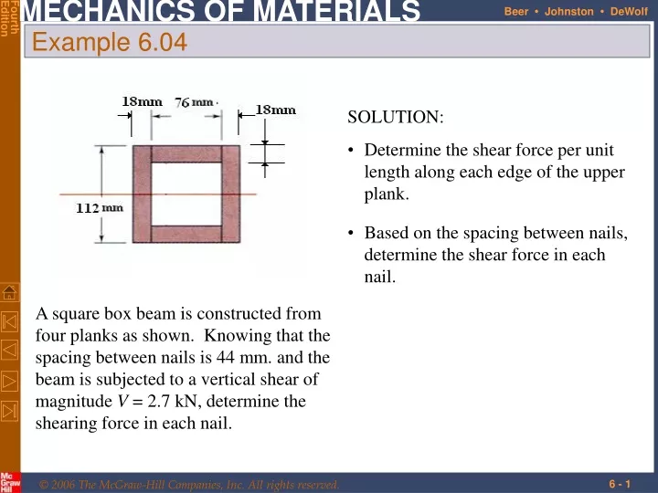
Example 6.04 • SOLUTION: • Determine the shear force per unit length along each edge of the upper plank. • Based on the spacing between nails, determine the shear force in each nail. A square box beam is constructed from four planks as shown. Knowing that the spacing between nails is 44 mm. and the beam is subjected to a vertical shear of magnitude V = 2.7 kN, determine the shearing force in each nail.
For the upper plank, For the overall beam cross-section, Example 6.04
Based on the spacing between nails, determine the shear force in each nail. Example 6.04 • SOLUTION: • Determine the shear force per unit length along each edge of the upper plank.
The longitudinal shear force on the element is • The corresponding shear stress is • Previously found a similar expression for the shearing stress in the web • NOTE: in the flanges in the web Shearing Stresses in Thin-Walled Members • Consider a segment of a wide-flange beam subjected to the vertical shear V.
The variation of shear flow across the section depends only on the variation of the first moment. Shearing Stresses in Thin-Walled Members • For a box beam, q grows smoothly from zero at A to a maximum at C and C’ and then decreases back to zero at E. • The sense of q in the horizontal portions of the section may be deduced from the sense in the vertical portions or the sense of the shear V.
Shearing Stresses in Thin-Walled Members • For a wide-flange beam, the shear flow increases symmetrically from zero at A and A’, reaches a maximum at C and then decreases to zero at E and E’. • The continuity of the variation in q and the merging of q from section branches suggests an analogy to fluid flow.
Recall: • For PL > MY , yield is initiated at B and B’. For an elastoplastic material, the half-thickness of the elastic core is found from • The section becomes fully plastic (yY = 0) at the wall when • Maximum load which the beam can support is Plastic Deformations • For M = PL < MY , the normal stress does not exceed the yield stress anywhere along the beam.
Preceding discussion was based on normal stresses only • Consider horizontal shear force on an element within the plastic zone, Therefore, the shear stress is zero in the plastic zone. • Shear load is carried by the elastic core, Plastic Deformations • As A’ decreases, tmax increases and may exceed tY
SOLUTION: • For the shaded area, • The shear stress at a, Sample Problem 6.3 Knowing that the vertical shear is 220 kN in a W250x101 rolled-steel beam, determine the horizontal shearing stress in the top flange at the point a located 108 mm from the edge of the beam.
If the shear load is applied such that the beam does not twist, then the shear stress distribution satisfies • F and F’ indicate a couple Fh and the need for the application of a torque as well as the shear load. • When the force P is applied at a distance e to the left of the web centerline, the member bends in a vertical plane without twisting. Unsymmetric Loading of Thin-Walled Members • The point O is referred to as the shear center of the beam section.
Beam loaded in a vertical plane of symmetry deforms in the symmetry plane without twisting. • Beam without a vertical plane of symmetry bends and twists under loading. Unsymmetric Loading of Thin-Walled Members
Determine the location for the shear center of the channel section with b = 100 mm., h = 150 ., and t = 4 mm. • where • Combining, Example 6.05
Shearing stresses in the flanges, • Shearing stress in the web, Example 6.06 • Determine the shear stress distribution for V = 11 kN.