Download
1 / 26
260 likes | 370 Views
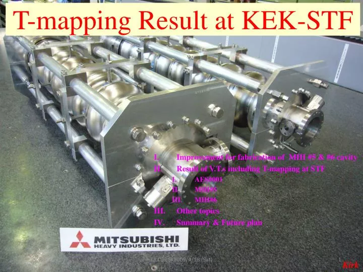
T-mapping Result at KEK-STF. Improvement for fabrication of MHI #5 & #6 cavity Result of V.T.s including T-mapping at STF AES#001 MHI#5 MHI#6 Other topics Summary & Future plan. Kirk. Improvement for fabrication of MHI #5 & #6 cavities. Thinning of equator thickness for EBW

E N D
T-mapping Result at KEK-STF Improvement for fabrication of MHI #5 & #6 cavity Result of V.T.s including T-mapping at STF AES#001 MHI#5 MHI#6 Other topics Summary & Future plan TILC09 @2009/4/18 (Sat) Kirk
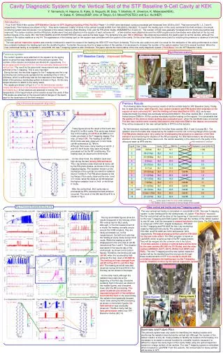
Improvement for fabrication of MHI #5 & #6 cavities • Thinning of equator thickness for EBW • CP before EBW in each step • Optimum EBW parameters for stable smooth surface • Clean environment around EBW device • Clean booth for assembly of EBW jigs • Check of EBW seam by Kyoto camera • We didn’t apply the barrel polish to these two cavities! Done at MHI! TILC09 @2009/4/18 (Sat)
Causes of Field Limit • Thermal quenching due to abnormal heating • Defect or contamination • Good correlation between the result of T-mapping and pass-band measurement • Not almost found suspicious spot at heating location • Field emission • Source of anxiety • Heating by electron bombardment, not defect or contamination • No correlation between the result of T-mapping and pass-band measurement • Multipacting(?) • Generally, multipacting location is not fixed • In our case, the cavity field gradually increases during multipacting and the barrier almost easily is overcome. • Unclear if it limits the cavity field or not • We think it is possible to overcome it for long RF conditioning TILC09 @2009/4/18 (Sat)
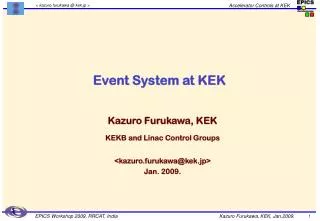
Cavity diagnostic system It is composed of the carbon resistors and PIN diodes. Fish-bone structure carbon resistor Pinpoint attachment ~300ch for C.R. 0.1sec sampling time PIN diode TILC09 @2009/4/18 (Sat)
Vertical Test Stand at STF TILC09 @2009/4/18 (Sat)
Case of AES #001 Cavity • Totally 3 times V.T.s • 1st : 11.2MV/m at π mode • Only HPR • 2nd : 15.7MV/m at π mode • Only HPR • 3rd : 21.8MV/m at π mode • EP(20μm) + HPR • Heating cells at π mode • #3(2nd V.T.), #3(3rd V.T.) • Suspicious spots • Two spots were found at #3 cell This is a very clear result. Thank you very much for FNAL’s people! TILC09 @2009/4/18 (Sat)
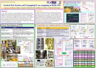
Result of T-mapping at 3rd V.T. for AES#001 Cavity 7π/9 8π/9 4π/9 6π/9 π π 3π/9 5π/9 Equator of #1 Cell π, 8π/9, 6π/9, 5π/9 Equator of #3 Cell 3π/9 Time [hour] Equator of #9 Cell TILC09 @2009/4/18 (Sat) Time [hour] Input Coupler Port
Comparison of Eacc, max for Each Cell Second Test Third Test The heating cell was not changed, although the gradient for each cell was increased. The EP(20μm) was not sufficient and more polish may be necessary. In the third test, other cells excluding #3 and #7 cell achieved above 30MV/m. TILC09 @2009/4/18 (Sat)
Case of MHI #5 Cavity • Totally 3 times V.T.s • 1st : 27.3MV/m at π mode • EP(50μm) + H2O2rinsing+HPR • Field flatness : 98.4% • 2nd : 19.7MV/m at π mode • EP(50μm) + H2O2rinsing+HPR • Field flatness : 97.1% • 3rd : 27.1MV/m at π mode • EP(20μm) +ethanol rinsing+ HPR • Field flatness : 96.9% • Heating cells at π mode • #5(1st V.T.), #8(2nd V.T.), #5(3rd V.T.) • Suspicious spots • Not found • (later presented by K. Watanabe) TILC09 @2009/4/18 (Sat)
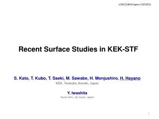
Result of T-mapping at 1st V.T. for MHI#5 Cavity 8π/9 6π/9 4π/9 π 5π/9 π 7π/9 3π/9 Limited by field emission @π mode expanded scale Equator of #1 Cell π, 3π/9 Equator of #5 Cell 4π/9 Equator of #9 Cell TILC09 @2009/4/18 (Sat) Input Coupler Port
Result of T-mapping at 2nd V.T. for MHI#5 Cavity another excitation 8π/9 6π/9 7π/9 5π/9 π 4π/9 π 3π/9 Equator of #1 Cell 5π/9 Equator of #3 Cell 7π/9 6π/9 π, 8π/9, 4π/9, 3π/9 Equator of #8 Cell Equator of #9 Cell TILC09 @2009/4/18 (Sat) Input Coupler Port
Result of Pass-band at 3rd V.T. for MHI#5 Cavity Preliminary! another excitation TILC09 @2009/4/18 (Sat)
Comparison of Eacc, max for Each Cell First Test Second Test Third Test The heating cell was changed from Cell #5 to #8 and to #5 again among these tests, but the limiting causes are different. 1st V.T. was limited by the field emission, and 2nd and 3rd V.T.s by the thermal quenching due to defect or contamination. We don’t understand the reason of the significant field degradation at 2nd V.T. Although each cell achieved above 30MV/m at 1st V.T., the field was limited 27.3MV/m due to the field emission in only π mode! TILC09 @2009/4/18 (Sat)
Case of MHI #6 Cavity • Totally 4 times V.T.s • 1st : 25.7MV/m at π mode • EP(50μm) +H2O2rinsing+HPR • Field flatness : 97.8% • 2nd : 24.6MV/m at π mode • Magnetic shield study • No surface process • No T-mapping • 3rd : 25.9MV/m at π mode • Magnetic shield study • No surface process • No T-mapping • 4th : 19.6MV/m at π mode • EP(50μm) + H2O2rinsing+HPR • Field flatness : 97.5% • Heating cells at π mode • #7(1st V.T.), #9(4th V.T.) • Suspicious spots • Not found • (later presented by K. Watanabe) 19.6MV/m 25.7MV/m No radiation TILC09 @2009/4/18 (Sat)
Result of T-mapping at 1st V.T. for MHI#6 Cavity 8π/9 7π/9 5π/9 4π/9 π π 6π/9 3π/9 Limited by field emission @π mode Equator of #1 Cell 3π/9 π Equator of #7 Cell Equator of #9 Cell TILC09 @2009/4/18 (Sat) Input Coupler Port
Result of T-mapping at 4th V.T. for MHI#6 Cavity 4π/9 8π/9 5π/9 π π 3π/9 6π/9 7π/9 Limited by multipacting(?) @π mode Equator of #1 Cell 3π/9 Equator of #5 Cell π~4π/9 It seems that the heating is gradually decreasing. We may overcome it, if we continue the test one more day. Equator of #9 Cell TILC09 @2009/4/18 (Sat) Input Coupler Port
Comparison of Eacc, max for Each Cell First Test Fourth Test The heating cell was changed from Cell #7 to #9, but the limiting cause was different. 1st V.T. was limited by the field emission and 2nd V.T. by the multipacting. We don’t understand the reason of the significant field degradation. Although each cell achieved above 30MV/m in 1st V.T., the field was limited 25.7MV/m due to the field emission in only π mode! TILC09 @2009/4/18 (Sat)
Summary of T-mapping result at STF T-mapping system at STF detected the heating cell for every V.T.s! TILC09 @2009/4/18 (Sat)
Other topics ①(Q0&Qt degradation) Q0 was degraded by 36% from 1st and 2nd π mode measurement. Qt was degraded by 7% from 1st and 2nd π mode measurement. Q0 was degraded by 50% from 1st and 2nd π mode measurement. Qt was degraded by 20% from 1st and 2nd π mode measurement. In every V.T.s at STF, two strange phenomena are observed. One is Q0 degradation. The other is Qt degradation. After many thermal quenching, both parameters are degraded. For Q0 degradation, it is considered that it is related to the magnetic field trapping at the quenching. The cable correction was no problem. TILC09 @2009/4/18 (Sat)
Other topics ②(a little heating before quenching) TILC09 @2009/4/18 (Sat)
Other topics ③(heating by electron bombardment at Top flange) #6 #5 #4 #3 #1 #2 TILC09 @2009/4/18 (Sat)
Summary & Future Plan • T-mapping system at STF is very useful and excellent, because it detected the heating location for every vertical test. • More R&D including the surface treatment is needed for the higher gradient at STF. • MHI #7, #8 and #9 cavities will be also tested at STF soon. • 4 cavities above 30MV/m will be prepared for S-1 Global project at STF by November. TILC09 @2009/4/18 (Sat)
Acknowledgement • For providing AES#001 Cavity • Dr. S. Mishra, Dr. B. Kephart, Dr. M. Champion and Dr. C. Ginsburg • For Carbon Resistors • Dr. H. Padamsee • Dr. W. Moeller • Dr. Y. Morita • For the assembly working of T-mapping • Mr. T. Okada and Mr. M. Iitake(K-Vac Co.) TILC09 @2009/4/18 (Sat)
Thank you for your attention! H. Hayano, E. Kako, Y. Kikuchi, S. Noguchi, M. Sato, T. Shishido, K. Umemori, K. Watanabe, Y. Yamamoto(KEK), H. Sakai(ISSP, Univ. of Tokyo) We will present these results in detail at PAC09! TILC09 @2009/4/18 (Sat)
Back-up slides TILC09 @2009/4/18 (Sat)
Result of T-mapping at 3rd V.T. for AES#001 Cavity 3π/9 #63 (Cell #8) #115 (Cell #5) #126 (Cell #5) TILC09 @2009/4/18 (Sat)