Download
1 / 28
280 likes | 438 Views
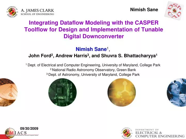
Nimish Sane. Integrating Dataflow Modeling with the CASPER Toolflow for Design and Implementation of Tunable Digital Downconverter. Nimish Sane 1 , John Ford 2 , Andrew Harris 3 , and Shuvra S. Bhattacharyya 1

E N D
Nimish Sane Integrating Dataflow Modeling with the CASPER Toolflow for Design and Implementation of Tunable Digital Downconverter Nimish Sane1, John Ford2, Andrew Harris3, and Shuvra S. Bhattacharyya1 1 Dept. of Electrical and Computer Engineering, University of Maryland, College Park 2 National Radio Astronomy Observatory, Green Bank 3 Dept. of Astronomy, University of Maryland, College Park 09/30/2009
Outline: • Motivation • Dataflow modeling • Tunable Digital Downconverter application • Design approach • Integration with CASPER toolflow CASPER Workshop 2009
Motivation: DSP systems • Efficient design and implementation of DSP systems: • Model based design approach • Exposure to underlying model of computation • High-level platform-independent abstraction and prototype CASPER Workshop 2009
Motivation: Dataflow modeling • Dataflow modeling used extensively for – • embedded systems for signal processing and communication applications • electronic design automation • Dataflow-oriented DSP design tools typically allow – • high-level application specification • software simulation • resource estimation • synthesis for hardware or software implementation • Leverage growing body of research in dataflow models of computation to the field of astronomical signal processing CASPER Workshop 2009
Dataflow-oriented tools: • Ptolemy (UC Berkeley) • Advanced Design System (Agilent Technologies) • LabVIEW (National Instruments) • CAL • SysteMoc • PEACE • Compaan/Laura • OpenDF • DIF (Dataflow Interchange Format) CASPER Workshop 2009
Dataflow modeling: • Data-driven execution • Data = Sequence of tokens; token is a data sample 1 2 1 3 A B C 2 • Actor • FIFO Buffer • Consumption Rate • Production Rate • Schedule [(3 ((2 A) BD)) C] D 2 Dataflow graph: synchronous dataflow (SDF) CASPER Workshop 2009 6
Parameterized Cyclo-static dataflow (CSDF) 1 control [1, 0, 0, …, 0]1 x D 1 1 1 [1 0 0 0] 1 A data D output B D IN OUT Decimator (CSDF) D = 4; phase = 0 Use Parameterized Dataflow Model (PDF) CASPER Workshop 2009 7
X CFDF C, BDF, DDF r e w X PCSDF o p X PSDF e v i s s X X X e MDSDF, WBDF CSDF, SSDF r CSDF p X x SDF E Verification / synthesis power Modeling Design Space CASPER Workshop 2009 8
Core Functional Dataflow (CFDF): • Restricted form of enable-invoke dataflow (EIDF) • Generalized DF model • Flexible and efficient prototyping • Natural description of actors for static and dynamic DF models • Transformations from other DF models into CFDF • Actor specification • enable function • invoke function • Set of modes CASPER Workshop 2009 9
control 1 1 [1,0] Control 1 out1 Switch True Output 1 [1,0] in 1 1 Switch [0,1] 1 [0,1] False Output 1 Data out2 Application Graph control control_true control_false Mode transition diagram between switch modes Actors in Functional DIF (Example: Switch) Switch Actor Production & consumption behavior of switch modes CASPER Workshop 2009 10
CFDF representation of tunable decimator 1 control [1, 0, 0, …, 0]1 x D 1 data output D D = 4 Each mode is annotated with number of tokens consumed from control and data inputs, and that produced on to the output D = 3 Mode Transitions for Decimator (CFDF) CASPER Workshop 2009 11
DIF based design flow CASPER Workshop 2009 12
Approach: CASPER Workshop 2009 13
Target application: Tunable digital downconverter (TDD) Part of Green Bank Ultimate Pulsar Processing Instrument (GUPPI), NRAO, Green Bank Observing at narrow bandwidths With same number of channels, this allows finer spectroscopy Downsampling the input signal to Nyquist rate for the chosen (narrow) BW Tunable digital downconverter (TDD) Support various TDD configurations Support tuning without re-synthesizing the hardware CASPER Workshop 2009 14
Block Diagram of Backend with TDD Band- width Band- width Center Frequency Center Frequency 8 output lines** 200 MS/s each Baseband Input BW = 800 MHz Baseband Input BW = 800 MHz To downstream signal processing units To downstream signal processing units 8-bit ADC (Sampling + Quantization) 8-bit ADC (Sampling + Quantization) Downconverter + Mixer Downconverter + Mixer XAUI_0* XAUI_0* XAUI_1* XAUI_1* Clock 800 MHz Clock 800 MHz ÷ 4 *XAUI : 10x Auxiliary User Interface port for streaming data over CX4 connectors of BEE2 and iBOB boards, with maximum data transfer capability of 10 Gbps. ** Each output line of ADC block has underlying 8 lines that output 8 bits in parallel *XAUI : 10x Auxiliary User Interface port for streaming data over CX4 connectors of BEE2 and iBOB boards, with maximum data transfer capability of 10 Gbps. CASPER Workshop 2009 15
Design specifications for TDD: • Input: • 800MHz baseband signal sampled at 1.6 GS/s, available over 8 ADC output lines • Each ADC output carries 200 MS/s, where each sample is 8-bit fixed point number. • Output: • Downsampled signal of pre-selected bandwidth and pass-band, to be fed to XAUI ports CASPER Workshop 2009
Design specifications for TDD: • Parameters: • Bandwidth (BW) and center frequency (CF) of the band • User specified • Parameters, once set by the user (observer), remain constant for a given observation session • BW may take values in the set {20, 40, 50, 80, 100, 200, 400, 64, 128, 240} MHz • Choice of CF will depend upon the BW, and possible values of CF for a given BW would ensure that entire spectrum is covered along with some overlap between the bands • Hardware Platform: • iBOB CASPER Workshop 2009
Tunable Digital Downconverter: ADC output 8 lines 200 MS/s each if output is baseband Baseband output Sample Rate Conv- erter (BW)* Mixer BPF (BW, CF)* Mixer Select (CF)* Switch (CF)* BPF (BW, CF)* Switch (CF)* Select (CF)* fLO (CF)* fLO (CF)* To XAUI Ports *parameters which affect the functional behavior of the block 8 lines each of 8-bit each CASPER Workshop 2009 18
{ } [1 0 0 0 0] 1 Sample Rate Converter 1/5 phase = 0 [0 1 0 0 0] 1 4 outputs 4 inputs [0 0 1 0 0] 1 1 [0 0 0 1 0] Functional DIF Prototype: • CFDF with PCSDF and PSDF as underlying dataflow models • Canonical scheduling • Simulation • Functional verification • Buffer sizes in terms of number of tokens CASPER Workshop 2009
TDD in Functional DIF CASPER Workshop 2009 20
Integration with CASPER toolflow/ Implementation in Simulink: • Emulating dataflow semantics in Simulink/Xilinx System Generator (XSG) • Developing actors/blocks currently not supported in XSG/CASPER/BEE_XPS libraries • Supporting parameterization without the need for synthesizing hardware each time the configuration of TDD changes CASPER Workshop 2009 21
Emulating Dataflow Semantics in Simulink/XSG: • Actors (Nodes) in DF graph Functional Simulink blocks • enable function: to determine whether the actor can be fired • invoke function: the actual functionality of the block • Edges in DF graph FIFO blocks in Simulink model • Size • Peek number of tokens in the buffer • Blocking read semantics • Implementation: dual port RAM block + wrapper to provide above features CASPER Workshop 2009 22
Parameterization for Simulink blocks: • Pre-synthesis • Parameterized subsystems with possible redrawing of underlying blocks • Masked subsystems with mask scripting • Post-synthesis • Support for tuning TDD parameters during run-time • Choice of frequency band determines parameters for underlying blocks • Use of software registers and PowerPC CASPER Workshop 2009 23
Conclusion: • Dataflow model based high-level application specification for • platform-independent prototype • functional simulation and verification • analysis (e.g. buffer sizes in terms of number of tokens) • benchmark for targeted platform-specific implementations • Integrating DIF based design approach with the CASPER toolflow • Porting DIF based prototype to Simulink/XSG • Emulating DF semantics in Simulink • Supporting parameterized actor blocks • Design is being currently integrated with the existing version of GUPPI CASPER Workshop 2009 24
Unit-testing: • DSPCAD Integrative Command-line Environment (DICE) • Cross-platform framework for unit-testing • DICELANG plug-ins for application language-specific project development (C, Java, Verilog, etc.) • Test – Fail – Edit – Compile – Test methodology CASPER Workshop 2009
Future work: • Using more efficient scheduling techniques and porting them to FPGA based platforms • Automated mapping of application-specification to platform-specific implementation CASPER Workshop 2009
Acknowledgement: • Randy McCullough, NRAO, Green Bank • Jason Ray, NRAO, Green Bank • Shilpa Bollineni, NRAO, Green Bank • Scott Ransom, NRAO, Charlottesville • Electronics and software divisions, NRAO, Green Bank CASPER Workshop 2009
References: [1] E. A. Lee and D. G. Messerschmitt, “Static scheduling of synchronous dataflow programs for digital signal processing”, in IEEE Transactions on Computers, 1996. [2] G. Bilsen, M. Engels, R. Lauwereins, and J. A. Peperstraete, “Cyclo-static dataflow”, in IEEE Transactions on Signal Processing, 1996, 44 (2), 397–408. [3] B. Bhattacharya and S. S. Bhattacharyya, “Parameterized dataflow modeling of DSP systems”, in Proceedings of the International Conference on Acoustics, Speech, and Signal Processing, 2000, pp. 1948–1951, Istanbul, Turkey. [4] W. Plishker, N. Sane, M. Kiemb, K. Anand, and S. S. Bhattacharyya, “Functional DIF for rapid prototyping”, in Proceedings of the International Symposium on Rapid System Prototyping, Jan 2008, pp. 17–23, Monterey, California. CASPER Workshop 2009