Download
1 / 21
220 likes | 340 Views
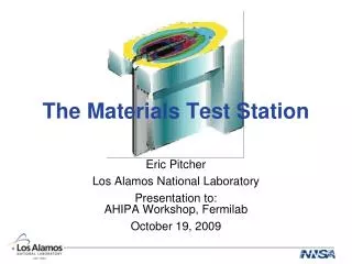
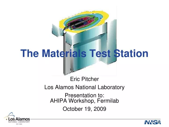
The Materials Test Station. Eric Pitcher Los Alamos National Laboratory Presentation to: AHIPA Workshop, Fermilab October 19, 2009. The MTS will be a fast spectrum fuel and materials irradiation testing facility . MTS will be driven by a 1-MW proton beam delivered by the LANSCE accelerator

E N D
The Materials Test Station Eric Pitcher Los Alamos National Laboratory Presentation to:AHIPA Workshop, Fermilab October 19, 2009
The MTS will be a fast spectrum fuel and materials irradiation testing facility • MTS will be driven by a 1-MW proton beam delivered by the LANSCE accelerator • Spallation reactions produce 1017 neutrons per second fuel module target module beam mask backstop
The MTS design includes all the services needed to maintain the target and change out samples servicecell • Beam raster system paints uniform beam spot on target • Independent fuel rodlet and sample can removal allows for short or long term irradiations • Irradiated samples are transferred to shipping casks in service cell targetchamber shield wall beamlineshield raster magnets
The MTS target consists of two spallation target sections separated by a “flux trap” materials sample cans tungsten spallation target test fuel rodlets • Neutrons generated through spallation reactions in tungsten • 2-cm-wide flux trap that fits 40 rodlets Beam pulse structure: 750 µs 7.6 ms 12 cm 16.7 mA Delivered to: left right left right target target target target 2 cm
The rastered beam provides nearly uniform current density over a 60 mm x 15 mm beam spot 21 mm wide target face 15 mm nominal spot width Proton Beamlet 3 mm FWHM horizontal 8 mm FWHM vertical Vertical slew covers 60 mm nominal spot height in 750 sec macro-pulse Fast raster is 20kHz sinusoid plus 8.8% 60kHz to make it more sawtooth shaped. Subsequent macropulses arrive at a different temporal phase, smearing the average spot vertically.
Horizontal cut through the target assembly at target mid-plane (magnified) backstop tungsten reflector material test specimen sample cans tungsten target fuel rodlets tungsten target beam mask shielding
Horizontal cut through the MTS target assembly at beam centerline – MCNP(X) model reflector materials samples spallation target proton beam 7 cm mask fuel samples backstop proton beam spallation target materials samples reflector
Spatial distribution of the proton flux shows low proton contamination in the irradiation regions
Spatial distribution of the fast neutron flux shows uniformity over the dimensions of a fuel pellet Fast (E>0.1 MeV) neutron flux
The neutron spectrum in MTS is similar to that of a fast reactor, with the addition of a high-energy tail p
MTS flux level is one-third to half of the world’s most intense research fast reactors *Accounts for facility availability.
Many MTS characteristics are substantially similar to a fast reactor • Same fission rate for fissile isotopes • For many fuel compositions the burnup evolution (actinide and fission product concentrations) is nearly the same • Uniform fission rate throughout the fuel pellet or slug • Clad irradiation temperature up to 550°C • Same radial temperature profile for a given linear heat generation rate and pellet/slug radius • Same burnup-to-dpa ratio
Principal differences between MTS and a fast reactor • High-energy tail of neutron spectrum • Pulsed nature of the neutron flux • Beam trips
High-energy tail of neutron spectrum produces differences from fast reactor irradiations • Higher helium production in steels • Known to embrittle austenitic steels operating above 0.5 Tm • Effect on ferritic/martensitic steels not yet well understood • 0.5 Tm is 550°C for SS316, 610°C for T91 • Higher helium production in oxide fuels from O(n,α) reactions • He production 2x greater than ABTR, but total gas production is only 10% greater • Higher Np production in fertile fuel from 238U(n,2n) reaction
Pulsed neutron flux issues • Temporal peak of the neutron flux is inversely proportional to the beam duty factor (7.5%) • Beam pulse repetition rate is 100 Hz • For oxide fuel, thermal cycling is not significant because thermal time constant (~100 ms) is much longer than the time between pulses (~10 ms) • Metal fuels may exhibit thermal cycling in MTS • Studies show that 100 Hz is nearly equivalent to steady-state with respect to bubble nucleation in steels
Accelerator beam trips are a potential issue for oxide fuel irradiation in MTS FRESH FUEL (OUT OF CORE) • Normal reactor conditions: • On startup, thermal stresses crack oxide pellets • Cracks in the columnar grain region heal during reactor operation • When reactor is shut down, pellets re-crack • The LANSCE accelerator will trip several times each day, during which the fuel temp drops to ~300°C • Cracks in the columnar grain region likely will not have time to fully heal between thermal cycles FRESH FUEL (ON STARTUP) 10 MWD/MT (IN CORE) 10 MWD/MT(OUT OF CORE) 100 MWD/MT (IN CORE) 1 GWD/MT (IN CORE)
The MTS neutron spectrum has potential application for fusion materials research * Data from U. Fischer et al., Fusion Engineering and Design 63-64 (2002) 493-500.
The damage rates for the MTS approach those observed in IFMIF and are 3 times ITER appm He/FPY* dpa/FPY* He/dpa ITER 1st wall 114 10.6 10.8 IFMIF HFTM (500 cc) 319 25.6 12.5 MTS (400 cc, fuel module) 266 24.9 10.7 IFMIF Li back wall 619 65.8 9.4 MTS (peak, fuel module) 393 33.9 11.6 *FPY = full power year; MTS expected operation is 4400 hrs per year. Values for MTS assume 1 MW of beam power.
At 1.8 MW, MTS provides nearly the same dose and irradiation volume as IFMIF MTS beam power = 1.8 MW MTS beam power = 1 MW
MTS project status • In November 2007, DOE-NE approved CD-0 for a “Fast Neutron Test Capability.” MTS was one of three alternatives identified to meet the need • In FY10 , MTS project expects to submit its CD-1 package for approval DOE-NE • Pending receipt of adequate funding and timely DOE approvals of Critical Decisions, MTS can start operating in 2015 • Current cost range for MTS is $60M to $80M • Project cost will be “baselined” during Conceptual Design
Summary • MTS is not fully prototypic of a fast reactor and is therefore not appropriate for providing final engineering data needed to qualify fast reactor fuel • Irradiation data obtained in MTS can advance our understanding of fuels and materials performance in a fast neutron spectrum • MTS irradiation data, coupled with data obtained from other irradiation facilities, can be used to validate simulation models • In addition to its primary mission of fission materials testing, MTS is well suited for irradiating fusion materials