Download
1 / 41
420 likes | 738 Views
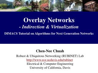
Overlay Networks and Tunneling Reading: 4.5, 9.4. COS 461: Computer Networks Spring 2009 (MW 1:30-2:50 in COS 105) Mike Freedman Teaching Assistants: Wyatt Lloyd and Jeff Terrace http://www.cs.princeton.edu/courses/archive/spring09/cos461/. Goals of Today’s Lecture.

E N D
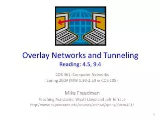
Overlay Networks and TunnelingReading: 4.5, 9.4 COS 461: Computer Networks Spring 2009 (MW 1:30-2:50 in COS 105) Mike Freedman Teaching Assistants: Wyatt Lloyd and Jeff Terrace http://www.cs.princeton.edu/courses/archive/spring09/cos461/
Goals of Today’s Lecture • Motivations for overlay networks • Incremental deployment of new protocols • Customized routing and forwarding solutions • Overlays for partial deployments • 6Bone, Mbone, security, mobility, … • Resilient Overlay Network (RON) • Adaptive routing through intermediate node • Multi-protocol label switching (MPLS) • Tunneling at L2.5
Overlay Networks Focus at the application level
IP Tunneling to Build Overlay Links A B E F A B E F tunnel Logical view: Physical view: • IP tunnel is a virtual point-to-point link • Illusion of a direct link between two separated nodes • Encapsulation of the packet inside an IP datagram • Node B sends a packet to node E • … containing another packet as the payload
Tunnels Between End Hosts B Src: A Dest: B Src: C Dest: B Src: A Dest: B A C Src: A Dest: C Src: A Dest: B
Overlay Networks • A logical network built on top of a physical network • Overlay links are tunnels through the underlying network • Many logical networks may coexist at once • Over the same underlying network • And providing its own particular service • Nodes are often end hosts • Acting as intermediate nodes that forward traffic • Providing a service, such as access to files • Who controls the nodes providing service? • The party providing the service • Distributed collection of end users
Using Overlays to Evolve the Internet • Internet needs to evolve • IPv6 • Security • Mobility • Multicast • But, global change is hard • Coordination with many ASes • “Flag day” to deploy and enable the technology • Instead, better to incrementally deploy • And find ways to bridge deployment gaps
6Bone: Deploying IPv6 over IP4 Flow: X Src: A Dest: F data Flow: X Src: A Dest: F data Flow: X Src: A Dest: F data Flow: X Src: A Dest: F data F A D C B F E B A E Src:B Dest: E Src:B Dest: E tunnel Logical view: IPv6 IPv6 IPv6 IPv6 Physical view: IPv6 IPv6 IPv6 IPv6 IPv4 IPv4 A-to-B: IPv6 E-to-F: IPv6 B-to-C: IPv6 inside IPv4 B-to-C: IPv6 inside IPv4
Secure Communication Over Insecure Links Encrypt packets at entry and decrypt at exit Eavesdropper cannot snoop the data … or determine the real source and destination
Communicating With Mobile Users www.cnn.com gateway • A mobile user changes locations frequently • So, the IP address of the machine changes often • The user wants applications to continue running • So, the change in IP address needs to be hidden • Solution: fixed gateway forwards packets • Gateway has a fixed IP address • … and keeps track of the mobile’s address changes
IP Multicast unicast multicast • Multicast • Delivering the same data to many receivers • Avoiding sending the same data many times • IP multicast • Special addressing, forwarding, and routing schemes
MBone: Multicast Backbone • A catch-22 for deploying multicast • Router vendors wouldn’t support IP multicast • … since they weren’t sure anyone would use it • And, since it didn’t exist, nobody was using it • Idea: software implementing multicast protocols • And unicast tunnels to traverse non-participants
Multicast Today • Mbone applications starting in early 1990s • Primarily video conferencing, but no longer operational • Still many challenges to deploying IP multicast • Security vulnerabilities, business models, … • Application-layer multicast is more prevalent • Tree of servers delivering the content • Collection of end hosts cooperating to delivery video • Some multicast within individual ASes • Financial sector: stock tickers • Within campuses or broadband networks: TV shows • Backbone networks: IPTV
Premise: by building application overlay network, can increase performance and reliability of routing RON: Resilient Overlay Networks Princeton Yale app-layer router Two-hop (app-level) Berkeley-to-Princeton route Berkeley http://nms.csail.mit.edu/ron/
RON Circumvents Policy Restrictions USLEC ISP Patriot PU me My home computer • IP routing depends on AS routing policies • But hosts may pick paths that circumvent policies
RON Adapts to Network Conditions B A C • Start experiencing bad performance • Then, start forwarding through intermediate host
RON Customizes to Applications B voice A bulk transfer C VoIP traffic: low-latency path Bulk transfer: high-bandwidth path
How Does RON Work? B A C • Keeping it small to avoid scaling problems • A few friends who want better service • Just for their communication with each other • E.g., VoIP, gaming, collaborative work, etc. • Send probes between each pair of hosts
How Does RON Work? B B A C • Exchange the results of the probes • Each host shares results with every other host • Essentially running a link-state protocol! • So, every host knows the performance properties • Forward through intermediate host when needed
RON Works in Practice • Faster reaction to failure • RON reacts in a few seconds • BGP sometimes takes a few minutes • Single-hop indirect routing • No need to go through many intermediate hosts • One extra hop circumvents the problems • Better end-to-end paths • Circumventing routing policy restrictions • Sometimes the RON paths are actually shorter
RON Limited to Small Deployments • Extra latency through intermediate hops • Software delays for packet forwarding • Propagation delay across the access link • Overhead on the intermediate node • Imposing CPU and I/O load on the host • Consuming bandwidth on the access link • Overhead for probing the virtual links • Bandwidth consumed by frequent probes • Trade-off between probe overhead and detection speed • Possibility of causing instability • Moving traffic in response to poor performance • May lead to congestion on the new paths
We saw tunneling “on top of” IP.What about tunneling “below” IP? Introducing Multi-Protocol Label Switching (MPLS)
Why Tunnel? • Reliability • Fast Reroute, Resilient Overlay Networks (Akamai SureRoute) • Flexibility • Topology, protocol • Stability (“path pinning”) • E.g., for performance guarantees • Security • E.g., Virtual Private Networks (VPNs) • Bypassing local network engineers • Censoring regimes: China, Pakistan, …
MPLS Overview • Main idea: Virtual circuit • Packets forwarded based only on circuit identifier Source 1 Destination Source 2 Router can forward traffic to the same destination on different interfaces/paths.
MPLS Overview • Main idea: Virtual circuit • Packets forwarded based only on circuit identifier Source 1 Destination Source 2 Router can forward traffic to the same destination on different interfaces/paths.
Circuit Abstraction: Label Swapping D • Label-switched paths (LSPs):Paths are “named” by the label at the path’s entry point • At each hop, MPLS routers: • Use label to determine outgoing interface, new label • Thus, push/pop/swap MPLS headers that encapsulate IP • Label distribution protocol: responsible for disseminating signalling information A 2 1 Tag Out New 3 A 2 D
Layer 3 Virtual Private Networks • Private communications over a public network • A set of sites that are allowed to communicate with each other • Defined by a set of administrative policies • Determine both connectivity and QoS among sites • Established by VPN customers • One way to implement: BGP/MPLS VPN (RFC 2547)
Layer 2 vs. Layer 3 VPNs • Layer 2 VPNs can carry traffic for many different protocols, whereas Layer 3 is “IP only” • More complicated to provision a Layer 2 VPN • Layer 3 VPNs: potentially more flexibility, fewer configuration headaches
Layer 3 BGP/MPLS VPNs VPN A/Site 2 10.2/16 VPN B/Site 1 10.2/16 CEA2 CE1B1 10.1/16 CEB2 VPN B/Site 2 P1 PE2 CE2B1 P2 PE1 PE3 CEA3 CEA1 P3 10.3/16 CEB3 10.1/16 VPN A/Site 3 10.4/16 VPN A/Site 1 VPN B/Site 3 • Isolation:Multiple logical networks over a single, shared physical infrastructure • Tunneling: Keeping routes out of the core BGP to exchange routes MPLS to forward traffic
High-Level Overview of Operation PE2 PE1 PE3 • IP packets arrive at PE • Destination IP address is looked up in forwarding table • Datagram sent to customer’s network using tunneling (i.e., an MPLS label-switched path)
BGP/MPLS VPN key components • Forwarding in the core: MPLS • Distributing routes between PEs: BGP • Isolation: Keeping different VPNs from routing traffic over one another • Constrained distribution of routing information • Multiple “virtual” forwarding tables • Unique Addresses: VPN-IPv4 extensions • RFC 2547: Route Distinguishers
Virtual Routing and Forwarding • Separate tables per customer at each router Customer 1 10.0.1.0/24 10.0.1.0/24RD: Purple Customer 1 Customer 2 10.0.1.0/24 Customer 2 10.0.1.0/24RD: Blue
Forwarding • PE and P routers have BGP next-hop reachability through the backbone IGP • Labels are distributed through LDP (hop-by-hop) corresponding to BGP Next-Hops • Two-Label Stackis used for packet forwarding • Top label indicates Next-Hop (interior label) • Second label indicates outgoing interface / VRF (exterior label) Corresponds to VRF/interface at exit Corresponds to LSP ofBGP next-hop (PE) Layer 2 Header Label1 Label2 IP Datagram
Forwarding in BGP/MPLS VPNs • Step 1: Packet arrives at incoming interface • Site VRF determines BGP next-hop and Label #2 Label2 IP Datagram • Step 2:BGP next-hop lookup, add corresponding LSP (also at site VRF) Label1 Label2 IP Datagram
Layer 3 BGP/MPLS VPNs VPN A/Site 2 10.2/16 VPN B/Site 1 10.2/16 CEA2 CE1B1 10.1/16 CEB2 VPN B/Site 2 P1 PE2 CE2B1 P2 PE1 PE3 CEA3 CEA1 P3 10.3/16 CEB3 10.1/16 VPN A/Site 3 10.4/16 VPN A/Site 1 VPN B/Site 3 BGP to exchange routes MPLS to forward traffic
Conclusions • Overlay networks • Tunnels between host computers • Build networks “on top” of the Internet • Deploy new protocols and services • Provide better control, flexibility, QoS, isolation, … • Underlay tunnels • Across routers within AS • Build networks “below” IP route • Provide better control, flexibility, QoS, isolation, … • Next time • Peer-to-peer applications